Edition: 04.2012 · 610.44436.40.
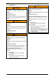
Contents Contents 1 Safety ..................................................................................................................................................3 1.1 Definitions .................................................................................................................................3 1.1.1 Safety alert symbol.......................................................................................................3 1.1.2 Signal words.........................................
Safety 1 Safety 1.1 CAUTION Danger of damage. Definitions Indicates a potentially hazardous situation that may result in property damage if the corresponding measures are not taken. To point out dangers and important information, the following signal words and symbols are used in these operating instructions: NOTICE 1.1.
Safety WARNING When working on the pump-motor unit, there is a danger of injury, e.g.
Safety WARNING Danger from rotating parts (external fan, impeller, shaft): Cutting/cutting off of extremities, Grasping/winding up of hair and clothing! Danger due to vacuum and gauge pressure: sudden escape of fluids (skin and eye injuries), sudden drawing in of hair and clothing! Danger due to escaping fluid: Burns! WARNING Danger of burns from hot surfaces of the pump-motor unit and from hot fluids! High temperatures of up to approx. +160°C [+320°F] can occur on the surface of the pumpmotor unit.
Safety 1.3 Residual risks WARNING WARNING Danger zone: Danger zone: Environment of pump-motor unit. Hot surface up to approx. +160°C [+320°F] Hazard: Hazard: Possible serious hearing damage due to emitted noise. Possible burns. Protective measures: Cover the pump-motor unit with a suitable touch protection (e.g. perforated plate cover or wire cover).
Intended Use 2 are primarily intended for higher pressure conditions; Intended Use These operating instructions apply to gas-ring vacuum pumps/compressors of the G-BH7 series, models 2BH72, 2BH73, 2BH74, 2BH75 and 2BH76, contains instructions concerning transport and handling, installation, commissioning, operation, shut-down, storage, servicing and disposal of the G-BH7, must be completely read and understood by all operating and servicing personnel before beginning to work with or on the G-BH7
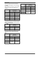
Technical Data 3 3.1 Minimum distances Technical Data Minimum distance to fan guard (for sucking in cooling air): Mechanical data Weight Single-impeller design Model Weight Model [mm] approx. [inches] approx. 2BH72 34 1.34 2BH73 34 1.34 [kg] approx. [lbs] approx. 2BH74 52 2.05 2BH7210-0..1.-. 16 35 2BH75 52 2.05 2BH7310-0..1.-. 16 35 2BH76 53 2.09 2BH7310-0..2.-. 17 38 2BH7410-0..1.-. 23 51 Minimum distance to face of vacuum pump/compressor cover: 2BH7510-0..1.-.
Technical Data Noise level Temperature increase Measuring-surface sound-pressure level as per EN ISO 3744, measured at a distance of 1 m [3.28 ft] at an operating point of approximately 2/3 of the permissible total pressure difference with the lines connected without a vacuum or pressure relief valve, tolerance ±3 dB (A).
Technical Data Tightening torques for screw connections The following values apply if no other information is available. With non-electrical connections, property classes of 8.8 and 8 or higher as per ISO 898-1 are assumed. Tightening torques for non-electrical connections Thread [Nm] [ft lbs] M4 2.7 - 3.3 1.99 - 4.44 M5 3.6 - 4.4 2.65 - 3.25 M6 7.2 - 8.8 5.31 - 6.5 M8 21.6 - 26.4 15.9 - 19.5 M10 37.8 - 46.2 27.9 - 34.1 M12 63.0 - 77.0 46.5 - 56.
Technical Data 3.2 Pressures Electrical data See rating plate. 3.3 Operating conditions Temperatures Temperature of pumped gases: max. permissible temperature: +40°C [+104°F] Nominal value: +15°C [+59°F] Pump-motor units for higher fluid temperatures on request. Ambient temperature (standard design)1: max. permissible temperature: +40°C [+104°F] Min. inlet pressure: See rating plate. Max. discharge pressure during compressor operation: See rating plate. Max. permissible 2.5 bar abs. [36.
Transport and Handling 4 The transport must be carried out in different ways depending on the model: Transport and Handling Models 2BH72., 2BH73., 2BH74. [singleimpeller] and 2BH75. [single-impeller]: Manual handling WARNING Tipping or falling can lead to crushing, broken bones etc.! Models 2BH74. [two-impeller], 2BH75. [twoimpeller] and 2BH76.
Installation 5 Installation WARNING Danger of fire from flammable substances! WARNING The pump-motor unit must never come into contact with flammable substances. Improper use of the unit can result in serious or even fatal injuries! Have you read the safety precautions in Chapter 1, "Safety", pg. 3 f.
Installation The pump-motor unit is ready to connect on delivery. The drive motors of the pump-motor units have the following design: However, if the time from delivery to commissioning of the pump-motor unit exceeds a certain period, the lubrication of the rolling bearings must be renewed. See Chapter 8.2, "Storage conditions", Section "Lubrication of rolling bearings after longer storage", Pg. 23 for information on this topic.
Installation Components for reducing noise on the pumpmotor unit: Vertical installation on the vacuum pump/compressor cover ("cover installation") Mufflers (included as standard equipment): On delivery the pump-motor units are equipped with attached mufflers as standard. The noise radiation is considerably reduced by the mufflers. See Fig. 2 to Fig. 4, Pg. 18 ff. With vertical installation of the pump-motor unit with the vacuum pump/compressor cover facing downward, rubber feet must be used.
Installation 5.2 Electrical connection (motor) Connection to drive-motor terminal box: Electrical danger! Open the required cable entry openings on the terminal box. Here the following two cases are differentiated: Improper behavior can result in severe injuries and material damage! The cable entry opening is prefabricated and provided with a sealing plug. DANGER Screw out sealing plug.
Installation For the tightening torques for terminal board connections (except terminal strips), see Chapter 3.1, "Mechanical data", Section "Tightening torques for screw connections", Pg. 10. Interference immunity of drive motor: For terminals with clamping straps (e.g. as per DIN 46282), the conductors must be inserted so that approximately the same clamping height results on both sides of the bar. Individual conductors must therefore be bent into a U-shape or connected with a cable lug (DIN 46234).
Installation 5.3 Connecting pipes/hoses (vacuum pump/compressor) WARNING Danger from rotating impeller: Cutting/cutting off of extremities! Mufflers: The pump-motor units are delivered with mufflers (indicated with arrows in the following illustrations) for the inlet and discharge connections as standard equipment. With single-impeller pump-motor units, the mufflers are already mounted on delivery.
Installation 5.3.1 WARNING Danger due to vacuum and gauge pressure! Danger due to escaping fluid! During operation, connected pipes and vessels are vacuumized or pressurized! Use only mounting elements, connections, lines, fittings and containers with sufficient freedom from leaks and strength for the pressures which occur.
Commissioning 6 6.1 Commissioning WARNING WARNING Danger from closed connections! Improper use of the unit can result in serious or even fatal injuries! Have you read the safety precautions in Chapter 1, "Safety", Pg. 3 f.
Commissioning WARNING WARNING Danger due to rotating parts! Danger due to vacuum and gauge pressure! Danger due to escaping fluid! Danger of hearing damage due to noise radiation! For the noise emission of the pump-motor unit measured by the manufacturer, see Chapter 3.1, "Mechanical data", Section "Noise level", Pg. 9. Test runs may also only be conducted with the pump-motor unit completely mounted.
Operation 6.2 Start-up and shut-down CAUTION Start-up Danger of rusting due to collection of condensed water in drive motor area! Open shut-off device in intake/discharge pipe. Switch on power supply for drive motor. On drive motors with closed condensed water openings: Remove closures occasionally to allow any water which has collected to drain off. Shut-down: Switch off power supply for drive motor. CAUTION Close shut-off device in intake/discharge pipe.
Servicing Provide mufflers on inlet and discharge side with sealing plugs. WARNING Improper use of the unit can result in serious or even fatal injuries! 8.
Servicing 9.1 Repairs/troubleshooting Fault Cause Remedy Carried out by Motor does not At least two power supply start; leads interrupted. no motor noise. Eliminate interruption by fuses, terminals or Electrician power supply cables. Motor does not One power supply lead start; humming interrupted. noise. Impeller is jammed. Eliminate interruption by fuses, terminals or Electrician power supply cables. Open vacuum pump/compressor cover, remove foreign body, clean.
Disposal 9.2 Service/After-sales service 10 Disposal Our Service is available for work (in particular the installation of spare parts, as well as maintenance and repair work), not described in these operating instruction. A list of spare parts with an exploded drawing is available on the Internet at www.gd-elmorietschle.com. Have the entire pump-motor unit scrapped by a suitable disposal company. No special measures are required when doing so.
EU declaration of conformity EU declaration of conformity EU declaration of conformity Manufacturer: Representative for the compilation of technical documents: Description and identification of the machine: Gardner Denver Deutschland GmbH Industriestraße 26 97616 Bad Neustadt • Germany Holger Krause Industriestraße 26 97616 Bad Neustadt • Germany Vacuum pumps/Compressors (Side channel blower) Series G-BH7 Types 2BH72..-.....-. 2BH73..-.....-. 2BH74..-.....-. 2BH75..-.....-. 2BH76..-.....-.
Form for statement on safety Form for statement on safety Statement on health safety and on the protection of the environment For the safety of our employees and to comply with statutory requirements on handling substances harmful to the health and the environment, this statement must be enclosed, fully completed, with each unit/system sent.
www.gd-elmorietschle.de er.de@gardnerdenver.com Gardner Denver Schopfheim GmbH Roggenbachstraße 58 79650 Schopfheim · Deutschland Tel. +49 7622 392-0 Fax +49 7622 392-300 Elmo Rietschle is a brand of Gardner Denver‘s Industrial Products Group and part of Blower Operations. Gardner Denver Deutschland GmbH Industriestraße 26 97616 Bad Neustadt · Deutschland Tel.