Edition: 03.2010 · 610.44440.40.000 Original operating instructions · English Operating instructions L-BV2, L-BV5 2BV2 06. 2BV2 07. 2BV5 11. 2BV5 121 2BV5 131 2BV5 161 2BV5 41. 2BV5 421 2BV5 47.
Contents Contents Layout of the units .............................................................................................................................. 3 1 Safety ..................................................................................................................................................4 1.1 Definitions .................................................................................................................................4 1.1.1 Warning symbol....................
Layout of the units Layout of the units 2BV2 0.. 1 7 8 9 6 2BV5 1.. 5 7 8 1 9 2 4 6 5 2BV5 4.. 2 7 8 9 4 3 1 6 2 4 610.44440.99.B01…B03 Fig. 1: Layout of the units Item Designation 2BV2 … 2BV5 1.. 2BV5 4..-.F 2BV5 4..-1G — 2BV5 110-….2-.S 2BV5 121-….2-.
Safety 1 Safety 1.1 CAUTION Definitions The following key words and symbols are used to impart warnings, important information and notes in these operating instructions: Danger of material damage. Indication of a possible danger which could lead to material damage if the appropriate precautions are not observed. CAUTION 1.1.1 Indication of a possible disadvantage, i.e. undesired circumstances may arise if the appropriate precautions are not observed.
Safety WARNING Working on the unit involves a risk of injury, e.g.
Correct use of the equipment 1.3 Other risks WARNING It is possible for long, loose hair to be drawn into the external fan through the grille in the fan guard! Wear a hair net! WARNING Long, loose hair can be caught and wound in by the rotation of the shaft between the motor end-shield and the pump casing. Wear a hair net! WARNING Injury can be caused by friction (abrasion, burning, etc.) against the rotating shaft between the motor end-shield and the pump casing.
Correct use of the equipment Foreseeable misuse The units create a vacuum or overpressure. are used to extract, deliver and compress the following gases / vapours: - - - The following are forbidden: all dry and humid gases, which are not explosive, flammable, aggressive or poisonous, Air or air-vapour mixtures. In the case of explosive, flammable, aggressive or poisonous gases / vapours, please consult the manufacturer. The gases / vapours must be free of solid matter.
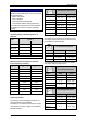
Technical data 3 Minimum clearances for heat dissipation Technical data 3.1 Type Mechanical data Minimum clearance Fan guard - adjacent surfaces [mm] [inches] 2BV2 060 34 1.34 2BV2 061 34 1.34 2BV2 070 53 2.09 Mass / Weight Type Weight* approx. [kg] approx. [lbs] 2BV2 060 Cast iron 25 55.5 2BV2 071 53 2.09 2BV2 061 Cast iron 26 57.5 2BV5 110 53 2.09 2BV2 070 Cast iron 35 77.5 2BV5 111 53 2.09 Stainless steel 42 93.0 2BV5 121 53 2.
Technical data Tightening torques for non-electrical connections ATTENTION If the permissible operating speed is exceeded this has a detrimental effect on the unit's operating characteristics: higher noise levels heavy vibrations reduced grease useful lifetime reduced time between changing bearings The maximum speed should not be exceeded, as damage can result from higher operating speeds. Thread [Nm] [ft lbs] M4 2.7 - 3.3 1.99 - 4.44 M5 3.6 - 4.4 2.65 - 3.25 M6 7.2 - 8.8 5.31 - 6.
Technical data Electrical data Pressures See motor rating plate. Operating conditions normal operation [mbar abs.] Temperatures max. achievable under-pressure (full throttling) Temperatures of the gases / vapours [°C] [°F] max. +80 [psia] max. +176 For higher media temperatures provisions have to be made in the system to protect against burning, e.g. fitting of guards. In this case one of the following provisions can be made: increase of the operating-liquid flow-rate to 2.
Technical data Min. suction pressure p1 min for operation without cavitation-protection* Cavitation-protection tapping closed [mbar abs.] [psia] 80 1.16 Max. permissible pressure within unit, pint max Type [bar abs.] [psia] As a general rule: The min. suction pressure will be the higher in dependence of the height of the temperature and the height of the vapour pressure of the operatingliquid used. The min.
Technical data Design operating-liquid flow [ft³/h] Type Flow rate Vacuum operation Flow rate, comin the pressure range [psi] pressor opera0.4792.90>7.25 tion 2.90 7.25 2BV2 060 7.06 7.06 7.06 7.06 2BV2 061 8.12 8.12 8.12 8.83 2BV2 070 9.89 / 12.0* 4.94 / 6.0* 4.94 / 6.0* 17.66 2BV2 071 15.89 8.12 9.89* 8.12 9.89* 24.72 2BV5 110 28.25 12.36 10.59 31.78 2BV5 111 42.38 14.13 12.36 42.
Transport 4 Transport WARNING Improper handling of the equipment can result in serious or even fatal injuries! Have you read the safety notes in chapter 1, "Safety", page 4 above? If not then you are not allowed to carry out any work on or with the equipment! WARNING Hazard presented by tilting or falling loads! Before transport, make sure that all the components are securely assembled and that all the components for which the fixings have been loosened are either properly secured or removed! CAU
Installation Transport of type 2BV5 …: 5 Installation Transport using crane and chains. the lifting points are the lifting eyes on the motor and one drilling in the discharge connection or the suction connection (Fig. 4 - Fig. 6, page 14). secure the chains to these lifting points. take care that the fittings are not damaged.
Installation Conditions for setting up the system: 5.2 The unit should be set up: The unit is supplied with all connection openings sealed off to prevent the ingress of foreign matter.
Installation 5.2.1 Connecting the suction and discharge connections CAUTION If the unit is connected to a vacuum tunnel the operating-liquid can be drawn out of the unit into the system risking damage to the system. Fit a check valve in the suction line. CAUTION The tightening torque for piping connections to the suction and discharge connections may not exceed 100 Nm [73.8 ft lbs]! The inlet connection (item 8, page 3) is marked with an arrow pointing downward.
Installation 5.2.3 Connecting up system components Operation with self-suction of the operatingliquid Connect up the components in accordance with the flow diagram shown below: 7 9 Operation with supply of the operating-liquid, automatically controlled operation 1 2 3 4 5 6 4 1 8 900 mbar abs 13.1 psia a 7 ≤1m ≤ 3.28 ft b 610.44440.99.B11 610.44440.99.
Installation 5.3 Connecting the electric motor 5.3.1 DANGER Connection to the motor terminal box WARNING Electrical hazard! Incorrect actions can lead to severe harm to persons and material damage! Electrical hazard! The air-gaps between non-insulated, energized components in relation to each other and to earth must be at least 5.5 mm [0.217"] (at a design voltage of UN ≤ 690V). No exposed wires are permissible. The electrical connections must be permanently secured.
Commissioning without testing by an appropriate inspection authority. 6 Commissioning WARNING 610.44440.99.B12 Fig.
Commissioning Take measures to ensure that the unit CANNOT be operated with the shut-off device closed. 6.3 Start-up of unit with self-suction of operating-liquid Fill up with operating-liquid Measure the motor insulation resistance. At values ≤ 1kΩ / Volt of measurement potential, dry the windings. Check the piping / hose connections for leaks.
Operation 7 7.1 Operation WARNING Improper handling of the equipment can result in serious or even fatal injuries! Have you read the safety notes in chapter 1, "Safety", page 4 above? If not then you are not allowed to carry out any work on or with the equipment! Operation with supply of the operatingliquid, automatically controlled operation Starting the unit up Switch on the power supply. The unit will start to draw in the gases / vapours to be handled. The solenoid valve (item 4, Fig.
Operation 7.3 Operation with self-suction of the operating-liquid When switching the unit on there should be a vacuum in the suction line (item 8, Fig. 10, page 17) of min. 900 mbar abs. [13.1 psia]. When switching on the liquid level in the supply line (item 7, Fig. 10, page 17) or in the storage vessel (item 9, Fig. 10, page 17) must be at the same level as the operating-liquid connection on the unit (item a, Fig. 10, page 17). During operation the liquid level in the storage vessel (item 9, Fig.
Decommissioning the machine and shutting it down for a longer period of time 8 Switch off the power supply. Take the abovementioned precautionary measures for safety when working on the unit or system. Place suitable drain-off containers underneath the cover. Open the screwed plugs in all drain tappings (item 4, page 3). Allow the liquid to drain off. Whilst doing so turn the shaft in its normal direction from time to time (Fig. 15, page 23).
Decommissioning the machine and shutting it down for a longer period of time 8.2 8.3 Preparations for long-term shutdown This chapter applies to: For longer shutdown periods (from approx. 4 weeks) or in the event of frost hazard proceed as follows: new units, units that have been prepared for long-term shutdown as described in chapter 8.2, "Preparations for long-term shutdown", page 24. Cast iron construction: Drain down the unit as described in chapter 8.1, "Draining down", page 23.
Maintenance 9 Maintenance WARNING Danger of burns or scalding from hot surfaces on the unit and from hot media! After shutdown, allow system to cool down! WARNING Improper handling of the equipment can result in serious or even fatal injuries! Have you read the safety notes in chapter 1, "Safety", page 4 above? If not then you are not allowed to carry out any work on or with the equipment! WARNING Hazard presented by rotation of the unit's impeller! Removal of the cover is forbidden! WARNING I
Maintenance 9.1 Maintenance Interval Maintenance procedure monthly check the piping and screwed joints for leakage and secure fixing then reseal and retighten them as necessary. monthly check the terminal box cover and cable entry openings for proper sealing and reseal if necessary.
Maintenance Interval Maintenance procedure Drain off the decalcifying liquid from the unit (see chapter 8.1, "Draining down", page 23). Flushing the pump casing(see page 26). Reconnect the piping / hoses. Start up the unit again (see chapter 6, "Commissioning", page 19). Dispose of the decalcifying agent in accordance with the applicable directives. 2.
Maintenance Fault Cause Correction Remedy Excessive backpressure in the discharge connection Reduce the backpressure. Operator Proportion of liquid entrained in the main flow is too high Reduce the proportion of liquid. Operator Impeller does not rotate freely See "Impeller does not rotate freely", page 27 Power con- Build up of lime-scale See "Decalcifying the unit", page 26. sumption or too high contamination See "Flushing the pump casing", page 26.
Disposal 9.3 The declaration of Clearance, Service / Customer service Our service department (ref. cover sheet of these operating instructions) is always available for work that is not described in these operating instructions (fitting of replacement parts and maintenance and repair work). When returning units to us: before dispatch: - - Drain down the unit completely as described in chapter 8.1, "Draining down", page 23.
EU declaration of conformity EU declaration of conformity EU declaration of conformity Manufacturer: Gardner Denver Deutschland GmbH P.O. Box 1510 D-97605 Bad Neustadt / Saale Responsible for documentation: Holger Krause P.O. Box 1510 D-97605 Bad Neustadt / Saale Designation: L Series Liquid ring vacuum pump/ compressor L-BV2, L-BV5 Types 2BV2 06., 2BV2 07., 2BV5 11., 2BV5 121, 2BV5 131, 2BV5 161, 2BV5 41., 2BV5 421, 2BV5 47.
Form for statement on safety Form for statement on safety Statement on health safety and on the protection of the environment For the safety of our employees and to comply with statutory requirements on handling substances harmful to the health and the environment, this statement must be enclosed, fully completed, with each unit/system sent.
www.gd-elmorietschle.de er.de@gardnerdenver.com Gardner Denver Schopfheim GmbH Roggenbachstraße 58 79650 Schopfheim · Deutschland Tel. +49 7622 392-0 Fax +49 7622 392-300 Elmo Rietschle is a brand of Gardner Denver‘s Industrial Products Group and part of Blower Operations. Gardner Denver Deutschland GmbH Industriestraße 26 97616 Bad Neustadt · Deutschland Tel.