
instructions Owner manual


Operation
© Gardner Denver Deutschland GmbH 21 / 32 610.44440.40.000
7 Operation
WARNING
Improper handling of the equipment can re-
sult in serious or even fatal injuries!
Have you read the safety notes in chapter 1,
"Safety", page 4 above?
If not then you are not allowed to carry out any
work on or with the equipment!
WARNING
Hazard in case of overpressure and negative
pressure!
Hazard presented by leaking media!
Hazard presented by moving parts!
The unit may only be started up if:
the fan guard and cover are fitted.
the piping is connected to the suction and
discharge connections.
the piping and connections have been pres-
sure and leak tested.
CAUTION
If the unit runs dry the rotary seals will be de-
stroyed within a matter of seconds.
DO NOT switch on until the system has been
filled with operating-liquid!
WARNING
Danger of burns or scalding from hot sur-
faces on the unit and from hot media!
Do not touch when in operation!
After shutdown, allow system to cool down!
ATTENTION
Maximum permissible quantity of water carried
along through the inlet connection:
see the table, "Maximum permissible quantity of
water carried along", page 12.
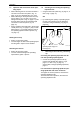
7.1 Operation with supply of the operating-
liquid, automatically controlled opera-
tion
Starting the unit up
Switch on the power supply.
The unit will start to draw in the gases / va-
pours to be handled.
The solenoid valve (item 4, Fig. 8, page 17)
opens and the operating-liquid is supplied.
Switching the unit off:
Switch off the power supply.
The unit interrupts suction of the gases / va-
pours.
The solenoid valve (item 4, Fig. 8, page 17)
closes and supply of the operating-liquid cea-
ses.
The throttle valve (item 3, Fig. 8, page 17) is
used for setting the operating-liquid flow rate:
during operational shutdown the valve-setting
(i.e. the position of the valve or the cross-
sectional area of the valve that is open) is not
to be changed.
7.2 Operation with supply of the operating-
liquid, non-automatic control of opera-
tion
Starting the unit up
The shut-off valve (item 4, Fig. 9, page 17) is
to be opened manually.
the operating-liquid is supplied.
switch on the power supply.
The unit will start to draw in the gases / va-
pours to be handled.
Switching the unit off:
Switch off the power supply.
The unit interrupts suction of the gases / va-
pours.
The shut-off valve (item 4, Fig. 9, page 17) is
to be closed manually.
supply of operating-liquid ceases.
The throttle valve (item 3, Fig. 9, page 17) is
used for setting the operating-liquid flow rate:
during operational shutdown the valve-setting
(i.e. the position of the valve or the cross-
sectional area of the valve that is open) is not
to be changed.