Edition: 1.12.
Table of contents Table of contents 1 Foreword . . . . . . . . . . . . . . . . . . . . . . . . . . . . . . . . . . . . . . . . . . . . . . . . . . . . . . . . . . . . . . . . . . . 4 1.1 1.2 1.3 1.4 1.5 1.6 1.7 1.8 Principles . . . . . . . . . . . . . . . . . . . . . . . . . . . . . . . . . . . . . . . . . . . . . . . . . . . . . . . . . . . . . . . . . . . Target group . . . . . . . . . . . . . . . . . . . . . . . . . . . . . . . . . . . . . . . . . . . . . . . . . . . . . . . . . . . . . . . . .
Table of contents 7 Maintenance and repair . . . . . . . . . . . . . . . . . . . . . . . . . . . . . . . . . . . . . . . . . . . . . . . . . . . . . . . 19 7.1 7.2 7.3 7.4 Ensuring operational safety . . . . . . . . . . . . . . . . . . . . . . . . . . . . . . . . . . . . . . . . . . . . . . . . . . . . . Maintenance work . . . . . . . . . . . . . . . . . . . . . . . . . . . . . . . . . . . . . . . . . . . . . . . . . . . . . . . . . . . . 7.2.1 Lubrication . . . . . . . . . . . . . . . . . . . . . . .
Foreword 1 Foreword 1.1 Principles These operating instructions: 1.2 • are a part of the following dry running rotary vane pressure vacuum pumps models VKTA 60/1 to V-KTA 140/3 and V-KTA 80/5. • describe how to use them safely and properly in all life phases. • must be available where the equipment is used. Target group The target group for these instructions is technically trained specialists. 1.3 Supplier documentation and accompanying documents Document Contents No.
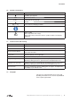
Foreword 1.6 Symbols and meaning Symbol Explanation Condition, pre-requisite #### a), b),... Instructions, action Instructions in several steps Results [-> 14] Cross reference with page number Information, note Safety symbol Warns of potential risk of injury Obey all the safety instructions with this symbol in order to avoid injury and death. 1.
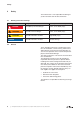
Safety 2 Safety The manufacturer is not responsible for damage if you do not follow all of this documentation. 2.1 Warning instruction markings Warning Danger level Consequences if not obeyed DANGER immediately imminent danger Death, severe bodily injury WARNING possible imminent danger Death, severe bodily injury CAUTION possible hazardous situation Slight bodily injury possible hazardous situation Material damage NOTICE 2.
Safety 2.3 Designated use The machine must only be operated in such areas as are described in the operating instructions: 2.4 • only operate the machine in a technically perfect condition • do not operate the machine when it is only partially assembled • the machine must only be operated at an ambient temperature and suction temperature of between 5 and 40°C. Please contact us for temperatures outside this range.
Safety 2.5 Personal qualifications and training • Ensure that people entrusted with working on the machine have read and understood these operating instructions before starting work, particularly the safety instructions for installation, commissioning, maintenance and inspection work.
Safety 2.8 2.9 Safety instructions for installing, commissioning and maintenance • The operator will ensure that any installation, commissioning and maintenance work is carried out by authorised, qualified specialists who have gained sufficient information by an in-depth study of the operating instructions. • Only work on the machine when it is idle and cannot be switched on again • Ensure that you follow the procedure for decommissioning the machine described in the operating instructions.
Transport, storage and disposal 3 Transport, storage and disposal 3.1 Transportation 3.1.1 Unpack and check the delivery condition a) Unpack the machine on receipt and check for transport damage. b) Notify the manufacturer of transport damage immediately c) Dispose of the packaging in accordance with the local regulations in force. 3.1.2 Lifting and transporting WARNING Death or limbs crushed as a result of the items being transported falling or tipping over.
Transport, storage and disposal 3.2 Storage NOTICE Material damage caused by improper storage. Ensure that the storage area meets the following conditions: a) dust free b) vibration free 3.2.1 Ambient conditions for storage Ambient conditions Value Relative humidity 0% to 80% Lagertemperatur -10°C to +60°C The machine must be stored in a dry environment with normal air humidity. It should not be stored for more than 6 months. see Info “Machine storage guidelines”, Page 4 3.
Set up and operation 4 Set up and operation 4.1 Setup P O Q N V-KTA /4 (04) F F E E A1 A2 B G F F E C1 C2 S D M V-KTA /4 (34) F A1 F E A2 B E F O F Fig.
Set up and operation 4.1.1 Data plate 1 3 2 Bauj./Nr. 09 4 5 3~ Mot. 2862775 Typ KTA 140 (34) 1022593431 +0,6 I -0,60 II -0,3 bar 140 m³/h EN 60034 S1 7,5 kW 10 Fig. 3 4.
Installation 5 Installation 5.1 Preparing for installation Check the following points: • • • • • Machine freely accessible from all sides Do not close ventilation grids and holes Sufficient room for installing and removing pipes and for maintenance work, particularly for installing and dismantling the machine No external vibration effects Do not suck any hot exhaust air from other machines into the cooling system. The filter housing (Fig. 2/S) should be easily accessible. The cooling air inlets (Fig.
Installation 5.3 Connecting pipes a) Vacuum connections at (Fig. 2/A1) ➝ higher vacuum and at (Fig. 2/A2) ➝ lower vacuum (second vacuum) as well as pressure connection at (Fig. 2/B). NOTICE Material damage resulting from the forces and torques of the pipes on the unit being too high Only screw pipes in by hand. Long and/or small bore pipework should be avoided as this tends to reduce the capacity of the machine.
Installation 5.5 Connecting the motor DANGER Danger of death if the electrical installation has not been done professionally. The electrical installation may only be done by a specialist electrician observing EN 60204. The operating company has to provide the main switch. a) The motor’s electrical data is given on the data plate (Fig. 2/N) or on the motor data plate. The motors comply with DIN EN 60034 and are in protection class IP 55 and insulation class F.
Commissioning and decommissioning 6 Commissioning and decommissioning 6.1 Commissioning WARNING Improper use May lead to severe or fatal injuries. Therefore be sure to obey the safety instructions. CAUTION Hot surfaces When the machine is at operating temperature the surface temperatures on the components (Fig. 2/ Q) may go above 70°C. You must avoid touching the hot surfaces (marked with warning plates).
Commissioning and decommissioning 6.1.1 Checking the rotation direction The drive shaft direction of rotation is shown by the rotation direction arrow (Fig. 2/O) on the motor flange. a) Start the motor briefly (max. two seconds) to check the direction of rotation. When looking at the motor fan, it must rotate clockwise. NOTICE Incorrect direction of rotation Running the machine in reverse for a long time may cause damage to the blades which may lead to the blades breaking.
Maintenance and repair 7 Maintenance and repair DANGER Danger of death from touching live parts. Before maintenance work disconnect the machine by pressing the main switch or unplugging it and ensure that it cannot be turned on again. WARNING Hot surfaces During maintenance work there is the danger of getting burnt on hot components (Fig. 2/Q) of the machine. Wait for the machine to cool down. 7.
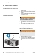
Maintenance and repair 7.2.1 Lubrication M w1 s L s L w1 G Fig. 4 Lubrication/ Blades G Inlet grating L Grease nipple M Grease recommendation plate s Screws w1 Slotted nut The bearings must be greased at the 2 greasing points (Fig. 4/L) with 6 g per point, after the following recommended operating hours or at the latest one year operation: 50 Hz: V-KTA 60 - 100 ➝ 10.000 h and V-KTA 140 ➝ 6.000 h 60 Hz: V-KTA 60 / 80 ➝ 10.000 h, V-KTA 100 ➝ 8.000 h and V-KTA 140 ➝ 4.
Maintenance and repair Changing blades: If the minimum height has already been reached or if the blades have fallen below this level the whole blade set must be changed. a NOTICE c Do not undo the slotted nuts (Fig. 4/w1) on the housing lid (Fig. 5/b). Only the screws (Fig. 4/s) need to be removed to change the blades. b G1 Before refitting the blades clean out the housing and the rotor slots with compressed air. Place the blades, with the radius outwards (Fig.
Maintenance and repair 7.2.3 Air filtering NOTICE Insufficient maintenance on the air filter The power of the machine lessens and damage may occur to the machine. The filter cartridges (Fig. 7/e) and (Fig. 7/f) must be cleaned by blowing through from the inside out once a month or more often depending on the level of contamination. In spite of cleaning the filters their separation efficiency will continue to deteriorate. Therefore the filters should be replaced every six months. The filter cartridges (Fig.
Maintenance and repair 7.2.4 Coupling The coupling rubbers (bb. 9/k) are wearing parts and should be checked regularly. When the coupling rubbers are worn this can be detected by a knocking sound when the pump is started. m l k p r CAUTION Defected coupling rubbers Defected coupling rubbers can cause extensive damage and even in some extreme cases break the rotor shaft. s5 n q l1 v Abb.
Maintenance and repair 7.3 Repair/ Service a) For on site repair work the motor must be disconnected from the mains by a qualified electrician so that it cannot be started up again accidentally. For repairs use the manufacturer, its branch offices or authorised dealers. Please contact the manufacturer for the address of the service centre responsible for you (see Manufacturer's address).
Maintenance and repair 7.4 Spare parts Order spare parts in accordance with the: • Spare parts list: E 457 ➝ V-KTA 60/4 - 140/4 (04) E 458 ➝ V-KTA 60/4 - 140/4 (34) • Download the PDF file: tp://www.gd-elmorietschle.com ➝ Downloads ➝ Product Documents ➝ V-Series ➝ Spare Parts • Parts subject to wear and gaskets are indicated separately on the list. • Web site: http://www.service-er.de • Select the type, size and design. NOTICE Fig.
Malfunctions: Causes and elimination 8 Malfunctions: Causes and elimination Fault Cause Troubleshooting Important Machine is switched off by the motor protection switch Mains voltage/ Frequency does not correspond with the motor data Check by qualified electrician Section 5.
Malfunctions: Causes and elimination Fault Cause Troubleshooting Important Overpressure or vacuum not achieved Machine or system leaking Check the pipework and screw connections for leaks and to ensure that they are firmly seated. Section 7.2 Discs are worn or damaged Replace discs Section 7.2.2 Section 7.4 Ambient or intake temperature is too high Ensure it is being used properly Section 2.3 Cooling air supply is obstructed Check environmental conditions Section 5.
Technical Data 9 Technical Data V-KTA /4 Sound pressure level (max.
www.gd-elmorietschle.com er.de@gardnerdenver.com Gardner Denver Schopfheim GmbH Roggenbachstraße 58 79650 Schopfheim · Deutschland Tel. +49 7622 392-0 Fax +49 7622 392-300 Elmo Rietschle is a brand of Gardner Denver‘s Industrial Products Division and part of Blower Operations.
EC - declaration of conformity 2006/42/EC Hereby the manufacturer confirms: Gardner Denver Schopfheim GmbH Postfach 1260 D-79642 Schopfheim that the machine: of the: Dry running pressure/vacuum pump Series: V-KTA Type: V-KTA 40/1, V-KTA 50/1, V-KTA 60/1, V-KTA 80/1, V-KTA 100/1, V-KTA 140/1 V-KTA 40/2, V-KTA 50/2, V-KTA 60/2, V-KTA 80/2, V-KTA 100/2, V-KTA 140/2 V-KTA 60/3, V-KTA 80/3, V-KTA 100/3, V-KTA 140/3 V-KTA 40/4, V-KTA 50/4, V-KTA 60/4, V-KTA 80/4, V-KTA 100/4, V-KTA 140/4 V-KTA 80/5 is conform
Safety declaration form for vacuum pumps and components 7.7025.003.17 Page 1 of 1 Gardner Denver Schopfheim GmbH Roggenbachstr. 58, 79650 Schopfheim Phone: +49/(0)7622/392-0 Fax: +49/(0)7622/392-300 Repairs and/or maintenance of vacuum pumps and components will only be carried out if a declaration has been filled in correctly and completely. If not, the repair work cannot be started and delays will result. This declaration must only be filled in and signed by authorised qualified staff. 1.