Hornet/Bee Digital Servo Drives for Extended Environmental Conditions Installation Guide February 2007 (Ver. 1.
Notice This guide is delivered subject to the following conditions and restrictions: This guide contains proprietary information belonging to Elmo Motion Control Ltd. Such information is supplied solely for the purpose of assisting users of the Hornet and Bee servo drives in their installation. The text and graphics included in this manual are for the purpose of illustration and reference only. The specifications on which they are based are subject to change without notice.
Hornet/Bee Installation Guide MAN-HRBEIG (Ver. 1.0) Contents Chapter 1: Safety Information ........................................................................................... 1-1 1.1 Warnings ............................................................................................................. 1-2 1.2 Cautions............................................................................................................... 1-2 1.3 Directives and Standards.........................................
Hornet/Bee Installation Guide Contents MAN-HRBEIG (Ver. 1.0) 3.10.1 3.10.2 3.10.3 3.10.4 Main and Auxiliary Feedback Combinations ...................................... 3-18 Auxiliary Feedback: Emulated Encoder Output Option (YA[4]=4) . 3-19 Auxiliary Feedback: Single-Ended Encoder Input Option (YA[4]=2) 3-21 Auxiliary Feedback: Pulse-and-Direction Input Option (YA[4]=0).. 3-23 3.11 I/Os………………………………….................................................................. 3-25 3.11.1 Digital Input............
Hornet/Bee Installation Guide Contents MAN-HRBEIG (Ver. 1.0) A.6.2.1 A.6.2.2 A.6.2.3 A.6.2.4 A.6.2.5 A.6.2.6 Incremental Encoder Input ................................................................................A-8 Digital Halls ........................................................................................................A-9 Interpolated Analog Encoder (Sine/Cosine)....................................................A-9 Resolver .............................................................
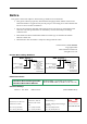
Hornet/Bee Installation Guide MAN-HRBEIG (Ver. 1.0) Chapter 1: Safety Information In order to achieve the optimum, safe operation of the Hornet and Bee servo drives, it is imperative that you implement the safety procedures included in this installation guide. This information is provided to protect you and to keep your work area safe when operating the Hornet and Bee as well as the accompanying equipment. Please read this chapter carefully before you begin the installation process.
Hornet/Bee Installation Guide Safety Information MAN-HRBEIG (Ver. 1.0) 1.1 Warnings To avoid electric arcing and hazards to personnel and electrical contacts, never connect/disconnect the servo drive while the power source is on. Power cables can carry a high voltage, even when the motor is not in motion. Disconnect the Hornet and Bee from all voltage sources before it is opened for servicing. The Hornet and Bee servo drives contain grounding conduits for electric current protection.
Hornet/Bee Installation Guide Safety Information MAN-HRBEIG (Ver. 1.0) 1.
Hornet/Bee Installation Guide Safety Information MAN-HRBEIG (Ver. 1.0) 1.5 Warranty Information The products covered in this manual are warranted to be free of defects in material and workmanship and conform to the specifications stated either within this document or in the product catalog description. All Elmo drives are warranted for a period of 12 months from the time of installation, or 18 months from time of shipment, whichever comes first.
Hornet/Bee Installation Guide Introduction MAN-HRBEIG (Ver. 1.0) Chapter 2: Introduction This installation guide describes the Hornet and Bee servo drives and the steps for its wiring, installation and power-up. Following these guidelines ensures maximum functionality of the drive and the system to which it is connected. 2.1 ExtrIQ Product Family Elmo Motion Control's ExtrIQ product family is a set of durable motion control products for applications operating under extreme environmental conditions.
Hornet/Bee Installation Guide Introduction MAN-HRBEIG (Ver. 1.0) • ISO-9001:2000 Based on Elmo Motion Control's innovative SimplIQ core technology, they support a wide range of motor feedback options, programming capabilities and communication protocols. 2.2 Drive Description The Hornet and Bee series are highly resilient digital servo drives designed to deliver “the highest density of power and intelligence”.
Hornet/Bee Installation Guide Introduction MAN-HRBEIG (Ver. 1.0) 2.3 Product Features 2.3.1 Current Control Fully digital Sinusoidal commutation with vector control or trapezoidal commutation with encoder and/or digital Hall sensors 12-bit current loop resolution Automatic gain scheduling, to compensate for variations in the DC bus power supply 2.3.
Hornet/Bee Installation Guide Introduction MAN-HRBEIG (Ver. 1.0) Automatic Correction of amplitude mismatch, phase mismatch, signals offset Auxiliary emulated, unbuffered, single-ended, encoder output • Resolver Programmable 10~15 bit resolution Up to 512 Revolution Per Second (RPS) Auxiliary emulated, unbuffered, single-ended, encoder output • Tachometer, Potentiometer • Elmo drives provide supply voltage for all the feedback options 2.3.
Hornet/Bee Installation Guide Introduction MAN-HRBEIG (Ver. 1.0) Chapter 3, Installation, provides step-by-step instructions for unpacking, mounting, connecting and powering up the Hornet and Bee. The Appendix, Technical Specifications, lists all the drive ratings and specifications. Upon completing the instructions in this guide, your Hornet and Bee servo drives should be successfully mounted and installed.
Hornet/Bee Installation Guide 3-1 MAN-HRBEIG (Ver. 1.0) Chapter 3: Installation 3.1 Site Requirements You can guarantee the safe operation of the Hornet and Bee by ensuring that they are installed in an appropriate environment. Feature Value Ambient operating temperature -40°C to +71°C (-40°F to 160°F) Maximum relative humidity 95% non-condensing Operating area atmosphere No flammable gases or vapors permitted in area The Hornet and Bee dissipate heat by convection.
Hornet/Bee Installation Guide Installation MAN-HRBEIG (Ver. 1.0) The part number at the top gives the type designation as follows: HOR- XX/YYY R Continuous Current (Amps) Maximum DC Operating Voltage Feedback: Blank = Incremental Encoder and/or Halls R = Resolver I = Interpolated Analog Encoder T = Tachometer & Potentiometer Verify that the Hornet or Bee type is the one that you ordered, and ensure that the voltage meets your specific requirements. 3.3 3.3.1 No.
Hornet/Bee Installation Guide Installation MAN-HRBEIG (Ver. 1.0) 3.3.
Hornet/Bee Installation Guide Installation MAN-HRBEIG (Ver. 1.0) 3.3.3 Connector J2 Pin Signal Function J2/1 +5V Encoder/Hall +5V supply voltage. Maximum output current: 200mA.
Hornet/Bee Installation Guide Installation MAN-HRBEIG (Ver. 1.0) Figure 3-1: 3.4.2 3-5 Hornet Footprint Bee The Bee was designed for mounting on a printed circuit board (PCB). It is connected by 2mm pitch 0.51 mm square pins. When designing the Bee into a device, be sure to leave about 1 cm (0.4") outward from the lower board to enable free air convection around the Bee. We recommend that the Bee be soldered directly to the board.
Hornet/Bee Installation Guide Installation MAN-HRBEIG (Ver. 1.0) 3.5 3-6 Integrating the Hornet or Bee on a PCB The Hornet and Bee are designed to be mounted on a PCB, either by soldering its pins directly to the PCB or by using suitable socket connectors. In both cases the following rules apply: 3.5.1 Traces 1. The size of the traces on the PCB (thickness and width) is determined by the current carrying capacity required by the application.
Hornet/Bee Installation Guide Installation MAN-HRBEIG (Ver. 1.0) 3-7 1. When wiring the traces of the above functions, on the Integration Board, the Returns of each function must be wired separately to its designated terminal on the Hornet or Bee. DO NOT USE A COMMON GROUND PLANE. Shorting the commons on the Integration Board may cause performance degradation (ground loops, etc). 2. Inputs: The 6 inputs are optically isolated from the other parts of the Hornet and Bee.
Hornet/Bee Installation Guide Installation MAN-HRBEIG (Ver. 1.0) 3.
Hornet/Bee Installation Guide Installation MAN-HRBEIG (Ver. 1.0) 3.7 Main Power and Motor Power Pin Function Cable VP+ Pos. Power input Power PR Power return Power PE Protective earth Power Pin Positions AC Motor DC Motor Motor Motor M1 Motor phase Motor N/C M2 Motor phase Motor Motor M3 Motor phase Motor Motor PE 3-9 Protective earth When connecting several drives to several motors, all should be wired in the same motor phases and feedback sequences.
Hornet/Bee Installation Guide Installation MAN-HRBEIG (Ver. 1.0) 3.7.2 3-10 Connecting Main Power Connect the VP+, PR and PE pins on the Hornet and Bee in the manner described in section 3.5 (Integrating the Hornet and Bee on a PCB). Figure 3-4: Main Power Supply Connection Diagram 3.8 Auxiliary Supply (for drive logic) Notes for 12 ~ 95 VDC auxiliary supply connections: Connect the VL and PR pins on the Hornet and Bee in the manner described in section 3.
Hornet/Bee Installation Guide Installation MAN-HRBEIG (Ver. 1.0) 3.8.1 3-11 Single Supply A single isolated DC power supply can provide power for both the main power and the Auxiliary (Drive Logic) Supply. The drawing below shows how a single supply is connected. Figure 3-5: Single Supply for both the Main Power Supply and the Auxiliary Supply 3.8.2 Separate Auxiliary Supply Power to the Auxiliary Supply can be provided by a separate Auxiliary Supply.
Hornet/Bee Installation Guide MAN-HRBEIG (Ver. 1.0) 3.8.3 Installation 3-12 Shared Supply A "Main" DC Power Supply can be designed to supply power to the drive's Logic as well as to the Main Power (see Figure 3-5). If backup functionality is required (for storing control parameters in case of power-outs) an additional backup supply can be connected by implementing 'diode coupling' (see the Aux. Backup Supply in Figure 3-7).
Hornet/Bee Installation Guide Installation MAN-HRBEIG (Ver. 1.0) 3.9 3-13 Main Feedback The Main Feedback port is used to transfer feedback data from the motor to the drive. In order to copy the setup to other drives, the phase order on all copy drives must be the same.
Hornet/Bee Installation Guide Installation MAN-HRBEIG (Ver. 1.
Hornet/Bee Installation Guide Installation MAN-HRBEIG (Ver. 1.
Hornet/Bee Installation Guide Installation MAN-HRBEIG (Ver. 1.
Hornet/Bee Installation Guide Installation MAN-HRBEIG (Ver. 1.0) 3-17 Figure 3-14: Main Feedback – Potentiometer Feedback Connection Diagram for Brush Motors and Voice Coils 3.10 Auxiliary Feedback For auxiliary feedback, select one of the following options: a. Single-ended emulated encoder outputs, used to provide emulated encoder signals to another controller or drive. The Emulated Encoder Output Option is only available when using a Resolver or Analog Encoder as the main feedback device.
Hornet/Bee Installation Guide Installation MAN-HRBEIG (Ver. 1.0) 3-18 3.10.1 Main and Auxiliary Feedback Combinations The Main Feedback is always used in motion control devices whereas Auxiliary Feedback is often, but not always used. The Auxiliary Feedback connector on the Hornet and Bee has three bi-directional pins (CHA, CHB and INDEX).
Hornet/Bee Installation Guide Installation MAN-HRBEIG (Ver. 1.0) 3.10.2 Auxiliary Feedback: Emulated Encoder Output Option (YA[4]=4) Pin Signal Function J1/4 SUPRET Supply return J1/19 INDEX+ Index output J1/18 CHBO Channel B output J1/5 CHAO Channel A output Pin Position Note: The Emulated Encoder Output Option is only available when using a Resolver or Analog Encoder as the main feedback device. Note: The Hornet and Bee's Auxiliary Feedback is single-ended.
Hornet/Bee Installation Guide Installation MAN-HRBEIG (Ver. 1.
Hornet/Bee Installation Guide Installation MAN-HRBEIG (Ver. 1.0) 3.10.3 3-21 Auxiliary Feedback: Single-Ended Encoder Input Option (YA[4]=2) Pin Signal Function J1/4 SUPRET Supply return J1/19 INDEX Auxiliary index input J1/18 CHB Auxiliary channel B input J1/5 CHA Auxiliary channel A input Pin Position Note: The Hornet and Bee's Auxiliary Feedback is singleended. When mounted on an integration board, circuitry can be added to make it differential.
Hornet/Bee Installation Guide Installation MAN-HRBEIG (Ver. 1.
Hornet/Bee Installation Guide Installation MAN-HRBEIG (Ver. 1.0) 3.10.4 Auxiliary Feedback: Pulse-and-Direction Input Option (YA[4]=0) Pin Signal Function J1/4 SUPRET Supply return J1/18 DIR/CHB Direction input (push/pull 5 V or open collector) J1/5 PULS/CHA Pulse input (push/pull 5 V or open collector) Pin Position Note: The Hornet and Bee's Auxiliary Feedback is singleended. When mounted on an integration board, circuitry can be added to make it differential.
Hornet/Bee Installation Guide Installation MAN-HRBEIG (Ver. 1.
Hornet/Bee Installation Guide Installation MAN-HRBEIG (Ver. 1.0) 3.11 I/Os The Hornet and Bee have 6 Digital Inputs, 2 Digital Outputs and 1 Analog Input. I/O J1 J2 Total Digital Input 6 - 6 Digital Output 2 - 2 Analog Input - 1 1 3.11.1 Digital Input Each of the pins below can function as an independent input.
Hornet/Bee Installation Guide MAN-HRBEIG (Ver. 1.
Hornet/Bee Installation Guide Installation MAN-HRBEIG (Ver. 1.0) 3.11.
Hornet/Bee Installation Guide Installation MAN-HRBEIG (Ver. 1.0) 3.11.
Hornet/Bee Installation Guide Installation MAN-HRBEIG (Ver. 1.0) 3.12 3-29 Communications The communication interface may differ according to the user’s hardware. The Hornet and Bee can communicate using the following options: a. RS-232, full duplex b. CANopen RS-232 communication requires a standard, commercial 3-core null-modem cable connected from the Hornet or Bee to a serial interface on the PC. The interface is selected and set up in the Composer software.
Hornet/Bee Installation Guide Installation MAN-HRBEIG (Ver. 1.0) 3-30 Figure 3-27: RS-232 Connection Diagram 3.12.2 CANopen Communication Notes for connecting the CANopen communication cable: Connect the shield to the ground of the host (PC). Usually, this connection is soldered internally inside the connector at the PC end. You can use the drain wire to facilitate connection. Ensure that the shield of the cable is connected to the shield of the connector used for communications.
Hornet/Bee Installation Guide Installation MAN-HRBEIG (Ver. 1.0) Figure 3-28: CANopen Network Diagram Caution: When installing CANopen communication, ensure that each servo drive is allocated a unique ID. Otherwise, the CANopen network may hang.
Hornet/Bee Installation Guide Installation MAN-HRBEIG (Ver. 1.0) 3.13 3-32 Powering Up After the Hornet or Bee is connected to its device, it is ready to be powered up. Caution: Before applying power, ensure that the DC supply is within the specified range and that the proper plus-minus connections are in order. 3.14 Initializing the System After the Hornet/Bee have been connected and mounted, the system must be set up and initialized.
Hornet/Bee Installation Guide Installation MAN-HRBEIG (Ver. 1.0) 3-33 External Heatsink Required Heatsink not Required Standard 40 °C Ambient Temp. External Heatsink Required Heatsink not Required 3.15.1.3 How to Use the Charts The charts above are based upon theoretical worst-case conditions. Actual test results show 30% - 50% better power dissipation. To determine if your application needs a heatsink: 1. Allow maximum heatsink temperature to be 80°C or less.
Hornet/Bee Installation Guide Installation MAN-HRBEIG (Ver. 1.0) 3-34 2. Determine the ambient operating temperature of the Hornet. 3. Calculate the allowable temperature increase as follows: • for an ambient temperature of 40°C , ΔT= 80°C - 40°C = 40 °C 4. Use the chart to find the actual dissipation power of the drive. Follow the voltage curve to the desired output current and then find the dissipated power. 5. If the dissipated power is below 4W the Hornet will need no additional cooling.
Hornet/Bee Installation Guide Hornet and Bee Technical Specifications MAN-HRBEIG (Ver. 1.0) Appendix: Hornet and Bee Technical Specifications A.1 Features A.1.1 Motion Control Modes • Current/Torque • Velocity • Position - A.1.2 up to 3.
Hornet/Bee Installation Guide Hornet and Bee Technical Specifications MAN-HRBEIG (Ver. 1.0) A-2 • Provide power (5V, 200mA max) for one Encoder, Resolver or Hall. A.1.6 Input/Output • One Analog Input – up to 14-bit resolution • Six programmable Digital Inputs, optically isolated (two of which are fast event capture inputs).
Hornet/Bee Installation Guide MAN-HRBEIG (Ver. 1.0) A.1.8 Accessories • Heat sinks (TBD) • Evaluation Board/Cable Kit A.1.9 • Status Indication Output for a bi-color LED A.1.10 Automatic Procedures • Commutation alignment • Phase sequencing • Current loop offset adjustment • Current loop gain tuning • Current gain scheduling • Velocity loop offset adjustment • Velocity gain tuning • Velocity gain scheduling • Position gain tuning A.2 Dimensions A.2.
Hornet/Bee Installation Guide Hornet and Bee Technical Specifications MAN-HRBEIG (Ver. 1.0) A.2.2 A-4 Bee A.3 Power Ratings A.3.1 Hornet Feature Unit 15/48 Minimum supply voltage VDC 6 7.5 12 Nominal supply voltage VDC 42 50 85 Maximum supply voltage VDC 48 59 95 Max.
Hornet/Bee Installation Guide Hornet and Bee Technical Specifications MAN-HRBEIG (Ver. 1.0) Dimensions 55 x 15 x 46.5 mm (2.2" x 0.6” x 1.8”) Digital In / Digital Out / Analog In 6/2/1 Mounting Method A.3.2 A-5 PCB Mount or soldered pins and 4 screws Bee Feature Unit 3/60 Minimum supply voltage VDC 7.5 12 Nominal supply voltage VDC 50 85 Maximum supply voltage VDC 59 95 Max.
Hornet/Bee Installation Guide Hornet and Bee Technical Specifications MAN-HRBEIG (Ver. 1.0) Condition Operating Condition -400 to 150,000m (-1,000 to 510,000 ft) Non-Operating Condition up to 95% relative humidity noncondensing at 35°C (95°F) Operating Condition up to 95% relative humidity noncondensing at 25°C (77°F), up to 90% relative humidity non-condensing at 42°C (108°F) Vibration Operating Condition 20 Hz -2000 Hz, 14.
Hornet/Bee Installation Guide Hornet and Bee Technical Specifications MAN-HRBEIG (Ver. 1.0) Feature Details Current loop bandwidth > 2.5 KHz Current sampling time Programmable 70 - 100 μsec Current sampling rate up to 16 KHz A.5.
Hornet/Bee Installation Guide Hornet and Bee Technical Specifications MAN-HRBEIG (Ver. 1.0) Feature Details Position loop bandwidth > 80 Hz Position sampling time 280 - 400 μsec (x 4 current loop sample time) Position sampling rate up to 4 KHz A.6 Feedbacks A.6.1 Feedback Supply Voltage The Hornet and Bee have two feedback ports (Main and Auxiliary). The drives supply voltage only to the main feedback device.
Hornet/Bee Installation Guide Hornet and Bee Technical Specifications MAN-HRBEIG (Ver. 1.0) Figure A-1: Main Feedback - Encoder Phase Diagram A.6.2.2 Digital Halls Feature Details Halls inputs HA , H B , H C. Single ended inputs Built in hysteresis of 1V for noise immunity Input voltage Nominal operating range: 0V < VIn_Hall < 5V Maximum absolute: -1V < VIn_Hall < 15V High level input voltage: V InHigh > 2.
Hornet/Bee Installation Guide Hornet and Bee Technical Specifications MAN-HRBEIG (Ver. 1.0) Feature Details Automatic errors correction Signal amplitudes mismatch Signal phase shift Signal offsets See Auxiliary Encoder Outputs specifications ( A.6.3) Encoder outputs A-10 A.6.2.4 Resolver Feature Details Resolver format Input resistance Differential 2.49 KΩ Resolution Programmable: 10 ~ 15 bits Maximum electrical frequency (RPS) 512 revolutions/sec Resolver transfer ratio 0.
Hornet/Bee Installation Guide Hornet and Bee Technical Specifications MAN-HRBEIG (Ver. 1.0) A.6.2.6 Potentiometer Feature Details Potentiometer Format Single-ended Operating Voltage Range 0 ~ 5V supplied by the Hornet and Bee Potentiometer Resistance 100Ω ~ 1 KΩ … above this range, linearity is affected detrimentally Input Resistance 100KΩ Resolution 14 Bit A.6.
Hornet/Bee Installation Guide Hornet and Bee Technical Specifications MAN-HRBEIG (Ver. 1.0) A.6.4 A-12 Auxiliary Feedback Port (input mode YA[4]= 2, 0) Feature Details Encoder input, pulse and direction input Output current capability A, B, Index Single ended VIn Low: 0V < VIL < 0.8V VIn High: 2V < VIH < 5V Maximum absolute voltage: 0 < VIn < 5.
Hornet/Bee Installation Guide Hornet and Bee Technical Specifications MAN-HRBEIG (Ver. 1.0) Feature Details High-level input voltage 2.
Hornet/Bee Installation Guide Hornet and Bee Technical Specifications MAN-HRBEIG (Ver. 1.0) A.7.2 Digital Output Interface Feature Details Type of output Optically isolated Open collector and open emitter Maximum supply output (Vcc) 30 V Max. output current Iout (max) (Vout = Low) Iout (max) ≤ 10 mA VOL at maximum output voltage (low level) Vout (on) ≤ 0.3 V RL External resistor RL must be selected to limit output current to no more than 10 mA.
Hornet/Bee Installation Guide Hornet and Bee Technical Specifications MAN-HRBEIG (Ver. 1.0) A-15 A.8 Communications Specification Details RS-232 Signals: RxD , TxD , Gnd Full duplex, serial communication for setup and control. Baud Rate of 9,600 ~ 57,600 bit/sec. CANopen CANbus Signals: CAN_H, CAN_L, CAN_GND Maximum Baud Rate of 1 Mbit/sec. Version: DS 301 V4.01 Layer Setting Service and Protocol Support: DSP 305 Device Profile (drive and motion control): DSP 402 A.
Hornet/Bee Installation Guide Hornet and Bee Technical Specifications MAN-HRBEIG (Ver. 1.0) IPC-D-275 IPC-SM-782 IPC-CM-770 UL508c UL840 In compliance with VDE0160-7 (IEC68) A.10.3 A-16 Reliability prediction of electronic equipment (rating, de-rating, stress, etc.) Printed wiring for electronic equipment (clearance, creepage, spacing, conductors sizing, etc.
Hornet/Bee Installation Guide Hornet and Bee Technical Specifications MAN-HRBEIG (Ver. 1.0) A-17 regulations * Please send out-of-service Elmo drives to the nearest Elmo sales office. A.10.9 RoHS Specification Description In compliance with 2002/95/EC (effective July 2006) Restrictions on Application of Hazardous Substances in Electric and Electronic Equipment This page was left blank intentionally.