
Installation guide


Whistle/Tweeter Installation Guide Installation
MAN-WHTWIG (Ver. 1.5)
3-11
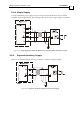
3.7.2 Connecting Main Power
Connect the VP+, PR and PE pins on the Whistle and Tweeter in the manner described in
section 3.5 (Integrating the Whistle and Tweeter on a PCB).
The source of the 12 ~ 95 VDC Main Power Supply must be isolated.
Figure 3-5: Main Power Supply Connection Diagram
3.8 Auxiliary Supply (for drive logic)
Notes for 12 ~ 95 VDC auxiliary supply connections:
The source of the 12 ~ 95 VDC Auxiliary Supply must be isolated.
Connect the VL and PR pins on the Whistle and Tweeter in the manner described in
section 3.5 (Integrating the Whistle and Tweeter on a PCB).
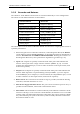
Pin Function Pin Positions
VL Auxiliary Supply Input
PR Supply Input Return
Caution:
Power from the Whistle and
Tweeter to the motor must come
from the Main Supply and NOT
from the Auxiliary Supply.
Table 3-2: Auxiliary Supply Pins