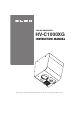
CEILING PRESENTER HV-C1000XG INSTRUCTION MANUAL Please read this instruction manual carefully before using this product and keep it for future reference.
IMPORTANT SAFEGUARDS ■ Read Instructions – All the safety and operating instructions should be read before the appliance is operated. ■ Retain Instructions – The safety and operating instructions should be retained for future reference. ■ Heed Warnings – All warnings on the product and in the operating instructions should be adhered to. ■ Follow Instructions – All operating and use instructions should be followed. ■ Cleaning – Unplug this product from the wall outlet before cleaning.
■ Grounding or Polarization – This product may be equipped with either a polarized 2-wire AC line plug (a plug having one blade wider than the other) or a 3-wire grounding type plug, a plug having a third (grounding) pin. The 2-wire polarized plug will fit into the power outlet only one way. This is a safety feature. If you are unable to insert the plug fully into the outlet, try reversing the plug. If the plug still fails to fit, contact your electrician to replace your obsolete outlet.
■ Damage Requiring Service – Unplug this product from the wall outlet and refer servicing to qualified service personnel under the following conditions: ● When the power-supply cord or plug is damaged. ● If liquid has been spilled, or objects have fallen into the product. ● If the product has been exposed to rain or water. ● If the product does not operate normally by following the operating instructions.
SA 1965 SA 1966 The lightning flash with arrowhead symbol, within an equilateral triangle, is intended to alert the user to the presence of uninsulated "dangerous voltage" within the product's enclosure that may be of sufficient magnitude to constitute a risk of electric shock to persons. This marking is located at the bottom of product.
BEFORE YOU USE ■ Use this product under the rated electrical conditions. ■ Do not leave this product under direct sunlight or by heaters, or this product may be discolored, deformed, or damaged. ■ Do not place this product in any humid, dusty, windy or vibrating location. Use this product in the following environmental conditions: Temperature: 5°C~40°C (41°F~104°F) Humidity: 30%~85% (No condensation) ■ Use a soft, dry cloth for cleaning. Do not use any volatile solvent, such as thinner or benzine.
CONTENTS 1. PART NAMES AND FUNCTIONS Appearance .......................................................8 Connector Panel ..................................................9 Wireless Remote Control .....................................10 2. WIRELESS REMOTE CONTROL Receivable Range ..............................................12 Preparation ......................................................12 1. PART NAMES AND FUNCTIONS 1 2. WIRELESS REMOTE CONTROL 2 3. MOUSE 3 4. INSTALLATION 4 5.
1. PART NAMES AND FUNCTIONS 1 2 2. WIRELESS REMOTE CONTROL 3 3. MOUSE CONTENTS 8. RS-232C SPECIFICATIONS Setting Up........................................................32 Cable Connection..............................................32 Connection ......................................................33 Transmission Specifications ..................................33 Data Format Specifications...................................33 Transmission command (PC → Ceiling Presenter) ..............
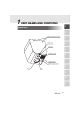
1 PART NAMES AND FUNCTIONS 1 Appearance 2 Ceiling mounting screw hole 3 Lamp cover 4 Setscrew 5 Ventilation outlet 6 7 Halogen lamp Infrared ray receptor 8 Lens LED 9 10 11 8
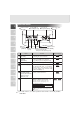
Connector Panel 1 Power Cord Receptacle[AC IN] Analog RGB-out Terminal [RGB OUT] RS-232C Terminal [RS-232C] Power Supply Switch [POWER] 2 3 A BCD 0 1 4 Mouse Terminal [MOUSE] 5 DIP Switches USB Terminal [USB] Name 6 9 10 11 Function Reference Page 1 RS-232C Terminal [RS-232C] To connect the RS-232C cable when controlling the unit from the PC. P.32 2 Analog RGB-out Terminal [RGB OUT] Image is output when this terminal is connected to RGB input equipment (e.g.
Name 7 8 Function Reference Page 1 Power Cord Receptacle Connected to the power cord connector. [AC IN] Power Supply Switch To turn ON/OFF the power supply. [POWER] 2 Wireless Remote Control 3 4 POWER 1 POWER 5 MEMORY NO. 3 2X 6 PRESET.SET 7 PRESET.CALL 10 POSI/NEGA 11 COLOR/B&W SET PRESET CALL SET IMAGE CALL POSI/NEGA COLOR/B&W CONTRAST LAMP IMAGE ROTATION F.A.M. MENU 14 MENU 17 ZOOM.TELE 18 ZOOM.WIDE 22 IRIS.NORMAL 23 IRIS.
Button Name 1 Function To turn ON/OFF the power supply. P.16 2 PAUSE To switch pause/motion of the image. P.21 3 DIGITAL 2X To double the image size. MAGNIFICATION ARROWS To scroll the magnified screen. This can 4 also be used to move the pointer when the pointer is displayed. 2 3 5 MEMORY NO. 4 5 6 7 8 9 10 11 11 Reference Page 1 POWER P.18 The memory No. Used with 6 to 9 . 6 STATUS PRESET.SET To store the operating condition of the unit. Used with the MEMORY NO. 7 PRESET.
2 WIRELESS REMOTE CONTROL 1 Receivable Range Point the infrared emitting part of the wireless remote control at the infrared sensor of this product, and press the button for desired function. The receivable range may be narrowed or the light may not be received when this product is placed under sunlight, near an inverter fluorescent lamp or in any other unfavorable surroundings. Take measures such as shielding the sunlight and the light from inverter fluorescent lamp.
1 3 MOUSE Mouse Operation Connect the mouse to the mouse terminal [MOUSE] on the connector panel. • Click the left button To operate the OSD menu. When digital magnification or image rotation (90°, 270°) is not used, the pointer and OSD menu can be displayed/deleted. • Drag by left button (moves while button is being pushed) In time of digital magnification or image rotation (90°,270°), screen is scrolled. • Click the mouse wheel To display or clear the pointer and OSD menu alternately by clicking.
4 INSTALLATION 1 Installation of the Unit For the ceiling mounting metal piece, VB-1000 separately available, any product approved by UL Standard for projector which is capable of supporting a load of 8-10 kg or more, or similar product also approved by UL Standard shall be used. Request your distributor to install this product on the ceiling. For details, refer to the HV-C1000XG Installation Manual included in the package.
Connection to Monitor and Projector 1 The following settings of this product can be made with the DIP Switches. Make the settings according to the connection environment.
5 OPERATION PROCEDURES 1 Simple Steps for Presenting Printed Material (1) Wireless remote control Push the [POWER] button of the wireless remote control to turn ON the power (Indicator LED on the unit turns from red to green). 2 (1) Connection with the monitor should be done in advance. POWER PAUSE (4) SET PRESET CALL SET If the Power Supply Switch is turned ON immediately after it is turned OFF, this product may not operate.
1 6 VARIOUS FUNCTIONS AND OPERATION Lighting Lighting for presenting information such as printed materials is provided. When the [LAMP] button on the wireless remote control is pressed, the lamp is lit. When the [LAMP] button is pressed again, the lamp goes off. 2 3 Wireless remote control POWER PAUSE SET PRESET CALL SET When the lighting provided by the unit is insufficient, use external lighting.
Digital Magnification To double the image, press the [2x] button on the wireless remote control or click the Right button of the mouse. Enlarged screen can be scrolled by operating the arrow button on the wireless remote control or by operating the mouse. 1 Wireless remote control 2 POWER PAUSE SET PRESET CALL SET IMAGE CALL POSI/NEGA COLOR/B&W CONTRAST If the OSD menu is displayed on the digitally magnified screen, the magnified screen cannot be scrolled by the wireless remote control.
Color / B&W Selection 1 Wireless remote control To present the B&W (Black&White) material such as documents. Sharper image with no color blur on the monitor can be produced. If the [COLOR/B&W] button on the wireless remote control is pressed, images are switched. 2 POWER PAUSE SET PRESET CALL SET IMAGE CALL POSI/NEGA COLOR/B&W CONTRAST When PAUSE is effective, COLOR/B&W selection does not work. 3 TELE LAMP IMAGE ROTATION F.A.M.
Posi / Nega Conversion 2 POWER PAUSE PRESET CALL SET TELE NEGA setting at the factory • Gamma: γ = 07 (0.3) • CONTRAST: ON IMAGE CALL SET POSI/NEGA COLOR/B&W CONTRAST LAMP IMAGE ROTATION F.A.M. MENU When using the NEGA conversion mode, use of the following is restricted. • With CONTRAST ON: Gamma adjustment is not available. • Only with Gamma setting γ = 07: CONTRAST can be turned ON. 1 Wireless remote control To show a negative film.
Pause 1 Wireless remote control When the [PAUSE] button on the wireless remote control is pressed, the image from the unit’s camera pauses. When the [PAUSE] button is pressed again, the PAUSE mode is canceled. 2 POWER PAUSE SET When PAUSE is effective, POSI/NEGA conversion, IMAGE ROATION, COLOR/B&W selection, F.A.M., and CONTRAST functions do not work. 3 Although the ZOOM, FOCUS, and IRIS functions are effective, the results are not reflected in the image in this mode.
F.A.M. (Frame Accumulate Mode) 1 Wireless remote control This is used to reduce artifacts of the image, and is appropriate to take pictures of still objects. Press the [F.A.M.] (Frame Accumulate Mode) button on the wireless remote control, and the [F.A.M.] is selected. Press the [F.A.M.] (Frame Accumulate Mode) button again, and the normal status is resumed. 2 POWER PAUSE SET PRESET CALL SET IMAGE CALL POSI/NEGA COLOR/B&W CONTRAST ZOOM WIDE TELE [F.A.M.
Focus 1 Wireless remote control Adjust the focus of the object. ■ Auto Focus 2 POWER When the [AF](AUTO FOCUS) button on the wireless remote control is pressed, the focus is set automatically. This product features a one-push AUTO FOCUS function. Once focusing is completed, the AUTO FOCUS function is released, and the focused position maintains unchanged (FOCUSFREE). 3 4 The objects listed below may not be brought into focus in the AUTO FOCUS mode. In these cases, use the MANUAL FOCUS mode.
■ Power Manual Focus Wireless remote control 1 To focus on specific part of the material, such as 3-D material. Press the FOCUS button [ FOCUS. NEAR] or [ FOCUS. FAR] on the wireless remote control. POWER PAUSE This product can finely adjust the focus. For minor adjustments, press the FOCUS button several times. For major adjustments, keep the FOCUS button pressed, then the focus begins to move more quickly. SET PRESET CALL SET LAMP IMAGE ROTATION F.A.M.
Preset Operation 1 Operation status of this product can be stored / read out in the memory (max. 8 states can be stored). Operation states that can be stored are as shown below. • Present zoom angle of view • Status of IRIS • White Balance status • ON/OFF of Aperture • Status of Gamma • Lighting status • Status of COLOR/B&W switch • Condition including pointer ON/OFF, color and shape • Condition of IMAGE ROTATION • ON/OFF of CONTRAST mode • Status of POSI/NEGA conversion • Status of F.A.M.
Image Memory 2 POWER PAUSE SET PRESET CALL SET IMAGE CALL POSI/NEGA COLOR/B&W CONTRAST TELE When the Power Supply is turned OFF by pressing the [POWER] button of the wireless remote control, the images stored in the memory are deleted. LAMP IMAGE ROTATION F.A.M. MENU 2. How to read out stored images Press the [IMAGE . CALL] button on the wireless remote control and press the MEMORY NO.
1 7 OSD (On-Screen Display) OSD (On-Screen Display) means the operating menu displayed on the screen (hereinafter called OSD menu). The OSD menu is operable by the wireless remote control or mouse. 2 OSD Operation 1. When the [MENU] button on the wireless remote control is pressed, a pointer is displayed. 2. If the [MENU] button is pushed again, the OSD menu is displayed, and the pointer moves to the lower left area of the OSD menu. 3. Move the pointer to the required icon.
Main Menu 1 2 3 Icon Name Function Reference Pages Lamp To turn ON/OFF the lighting. When power is turned ON, the previous saved setting remains. P.17 Color/B&W selection To switch the selection of the Color/B&W of the screen. When power is turned ON, the previous saved setting remains. P.19 To switch the selection of the positive/negative of the screen. When power is turned ON, the previous saved setting remains. P.20 To rotate the image counterclockwise by 90°.
Icon 1 Name Function Status saving To save initial status when power is turned ON. For the mouse pointer ON/OFF selection the same items stored in the Preset/Move operation are saved. Initialization To reset this product to the status of the factory settings. Focus Near/Far To adjust the focus . Auto Focus To focus automatically. Zoom Tele/Wide To adjust the zoom of the lens. Iris Close/Open To adjust the iris of the lens. 2 Reference Pages P.25 3 4 5 6 P.24 P.23 P.
Sub Menu ● White Balance Adjustment menu ● Gamma menu 1 ● Power Supply Off Timer 2 3 Icon Name White Balance Auto Function 4 Reference Page To display the White Balance Adjustment menu. When this button is pressed again, the White Blance Adjustment menu is closed. 5 To set the White Blance in the AUTO FOLLOW mode. (initial setting) One-push To set the push-set White Blance. When this button is pressed the white balance for the then color temperature is fixed.
Icon 1 Name Gamma adjustment Power Supply Off Timer Sets the time between end of operation and power OFF. The time can be set within the range from 01 (1h) to 08 (8h). When 00 is set, the timer does not operate. If Power Supply is turned OFF, the indicator LED turns orange. 2 3 4 5 6 7 8 9 10 11 31 Function To change the Gamma setting value (00(1.0) / 01(0.9) / 02(0.8) / 03(0.7) / 04(0.6) / 05(0.5) / 06(0.4) / 07(0.3)). The factory setting is “04 (0.6).
8 RS-232C SPECIFICATIONS 1 This product can be controlled by a PC connected through the RS-232C terminal [RS-232C]. Setting Up (1) 2 Connect this product to a PC with an RS-232C connection cable. When using an RS-232C cable available in the market, select a cable with the connection shown below. 3 To protect this product and the PC, be sure to turn OFF all the power supply of all equipment before connecting.
Connection 1 If the RS-232C cable is not correctly connected between this product and the PC, no acknowledgement is transmitted. Connect the RS-232C cable correctly, and fix it firmly with the connector set screws before the operation. 2 Transmission Specifications 3 • • • • • • • 4 5 Full duplex start-stop sync.
■ Response data format (Ceiling Presenter→ PC) 1 All response data is transmitted as ASCII code, and it covers parameter of the table of operation command table. • Status 0 S T X Lamp on/off 30H Posi / Nega Color Pointer Digital Pause / B&W display Magnification Local lockout E T X 30H (Normal) 31H (Adjustment) E T X 2 • Status 2 S T X 32H γ Image White Contrast adjustment rotation Aperture Balance 30H 3 4 • Status 7 S T X F.A.M.
UART Communication Format 1 Commands, parameters and data are all transmitted in ASCII code.
Function F.A.M. selection Image Store Image Read Command Parameter CL 0 (OFF) 1 (ON) IS IC Data 1 2 3 4 5 6 7 8 1 2 3 4 5 6 7 8 0 ■■ 3 ■■ 4 AV Contrast CT 0 (OFF) 1 (ON) ■■ Local Lockout LL 0 (OFF) 1 (ON) ■■ Default DF 0 ■■ Status request QS 0 2 7 8 0 ■■ ■■ • To finish the IMAGE CALL mode and go back to the normal camera image.
1 9 REPLACING THE LAMP Replacing the Lamp The lamp that is installed in the product has a certain life span. When the lamp is used for a long period, the lamp light may become dark or the lamp may go off due to the end of its life. (The life of the lamp varies according to the utilization condition.) In this case, replace the lamp. 2 How to replace the lamp 3 WARNING • Use JR12V50W AKM/5EZ-1 manufactured by Phillips for replacement. Other lamps may blow out or cause fire if used.
10 TROUBLESHOOTING HINTS 1 Symptoms and Confirmation Check the following items. If any abnormality is found, consult the seller or our branch/office in your area. Symptom No image on TV monitor. Out of focus Possible cause / countermeasure • Cable is not properly connected to the video-in terminal of monitor. • The power cord is disconnected from the wall AC outlet. • The plug is disconnected from the power cord receptacle of this product. • The power switch is not turned ON.
1 11 SPECIFICATIONS ■ General Item 2 3 4 Specifications Power source Rated current Dimensions (W × D × H) AC100 - 240V 50Hz/60Hz 1.2 - 0.6A 226mm × 226mm × 239mm (8.9 × 8.9 × 9.4 in.) Weight 6.5 kg (14.3 lbs.) (main body only) Output terminal RGB output Composite Video output S-Video output RS-232C Mouse Ext.
■ Camera Item 1 Specifications Lens Frame rate Shooting area(H × V) (Projection -> photographing distance: 2m(78.7in)) f = 14.2 – 170mm (12 - time zoom), F2.6 – 2.7 20 frames / sec 662mm × 511mm (26.0 × 20.1 in.) max. 53mm × 41mm (2.1 × 1.6 in.) min. Limit of focus adjustment Distance from the unit to the text (object of shooting): Zooming Focusing Iris Image pick-up device Total pixels Effective pixels Sync.
■ Supplied Accessories 1 Name Power cord (2.5m) Video cable (RCA pin connector) (3 m) S-Video cable (Mini DIN 4P connector) (2 m) Infrared wireless remote controller (RCW-C1000) Batteries (Type R03, AAA) Analog RGB cable (DSUB 15P connector) (2 m) Analog RGB cable (BNC connector) (1.8 m) Instruction manual Installation manual Warranty card Scroll mouse USB cable (1.8m) Utility Software CD-ROM Utility Software Installation Manual C.
[MEMO]
WARNING Unauthorized recording of copyrighted slide films, materials, photographs, etc. may infringe on the rights of copyright owners and be contrary to copyright laws. ELMO CO., LTD. 6-14, Meizen-cho, Mizuho-ku, Nagoya, 467-8567, Japan OVERSEAS SUBSIDIARY COMPANIES U.S.A. ELMO Mfg. Corp. 1478 Old Country Road, Plainview, NY 11803-5034 Tel:(516)501-1400 Fax:(516)501-0429 E-mail: elmo@elmousa.com Web: http://www.elmousa.com/ Canada ELMO Canada Mfg. Corp.