Dragonfly/Butterfly Current Mode Servo Amplifiers for DC Brush and Brushless Motors with Trapezoidal Commutation in Extended Environmental Conditions Installation Guide April 2008 (Ver. 1.1) www.elmomc.
Notice This guide is delivered subject to the following conditions and restrictions: This guide contains proprietary information belonging to Elmo Motion Control Ltd. Such information is supplied solely for the purpose of assisting users of the Dragonfly and Butterfly servo drives in their installation. The text and graphics included in this manual are for the purpose of illustration and reference only. The specifications on which they are based are subject to change without notice.
Dragonfly/Butterfly Installation Guide MAN-DRBUIG (Ver. 1.1) Contents Chapter 1: Safety Information ............................................................................................... 1-1 1.1 Warnings.................................................................................................................... 1-2 1.2 Cautions ..................................................................................................................... 1-2 1.3 Directives and Standards ..............
Dragonfly/Butterfly Installation Guide Contents MAN-DRBUIG (Ver. 1.1) 4.2.4 4.2.5 4.2.6 External Voltage................................................................................................ 4-2 External Resistor ............................................................................................... 4-3 Latch Mode (LM) .............................................................................................. 4-3 4.3 Status Indications ..............................................
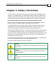
Dragonfly/Butterfly Installation Guide MAN-DRBUIG (Ver. 1.1) Chapter 1: Safety Information In order to achieve the optimum, safe operation of the Dragonfly and Butterfly servoamplifiers, it is imperative that you implement the safety procedures included in this installation guide. This information is provided to protect you and to keep your work area safe when operating the Dragonfly and Butterfly and accompanying equipment. Please read this chapter carefully before you begin the installation process.
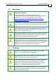
Dragonfly/Butterfly Installation Guide Safety Information MAN-DRBUIG (Ver. 1.1) 1.1 Warnings Cleaning after soldering To avoid the damage of the product's acrylic coating the Dragonfly/Butterfly must not be cleaned after soldering by dissolving solvents and /or "water" cleaning process. For more details: http://www.elmomc.com/applications/article/Soldering-andCleaning_Application-Note.
Dragonfly/Butterfly Installation Guide Safety Information MAN-DRBUIG (Ver. 1.1) 1.
Dragonfly/Butterfly Installation Guide Safety Information MAN-DRBUIG (Ver. 1.1) 1.5 Warranty Information The products covered in this manual are warranted to be free of defects in material and workmanship and conform to the specifications stated either within this document or in the product catalog description. All Elmo drives are warranted for a period of 12 months from the time of installation, or 18 months from time of shipment, whichever comes first.
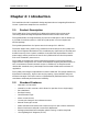
Cymbal Installation Guide Introduction MAN-CYMIG (Ver. 1.1) Chapter 2: Introduction This Installation Guide is intended for design engineers who are integrating Elmo Motion Control Cymbal servo amplifiers into a machine. 2.1 Product Description The Cymbal series of servo amplifiers is designed to operate in the current mode controlling permanent-magnet trapezoidal brushless motor and DC brush motor. The Cymbal exhibits “the highest density of power and intelligence” and can deliver up to 11.
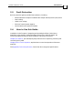
Cymbal Installation Guide Introduction MAN-CYMIG (Ver. 1.1) 2.3 Fault Protection Built-in protection against possible fault conditions, including: • Shorts between the outputs or between each output and the power input/return • Over-heating • Under/over voltage • Failure of internal power supplies • Latch mode for each protective feature 2.4 How to Use this Guide Installation is the first step in integrating and operating the Elmo Cymbal servo amplifiers.
Dragonfly/ Butterfly Installation Guide Installation MAN-DRBUIG (Ver. 1.1) 3-1 Chapter 3: Installation 3.1 Before You Begin 3.1.1 Site Requirements You can guarantee the safe operation of the Dragonfly and Butterfly by ensuring that they are installed in an appropriate environment.
Dragonfly/ Butterfly Installation Guide Installation MAN-DRBUIG (Ver. 1.1) 3-2 DRA- X/YY Continuous Current (Amps) Maximum DC Operating Voltage 3. Verify that the Dragonfly or Butterfly type is the one that you ordered, and ensure that the voltage meets your specific requirements. 3.3 3.3.
Dragonfly/ Butterfly Installation Guide MAN-DRBUIG (Ver. 1.1) 3.3.2 Installation 3-3 Dragonfly Dimensions Figure 3-2: Dragonfly Dimensions 3.4 3.4.1 Mounting Butterfly The Butterfly was designed for mounting on a printed circuit board (PCB). It is connected by 2mm pitch 0.51 mm square pins. When designing the Butterfly into a device, be sure to leave about 1 cm (0.4") outward from the heatsink to enable free air convection around the Butterfly.
Dragonfly/ Butterfly Installation Guide Installation MAN-DRBUIG (Ver. 1.1) 3.5 3-4 Integrating the Dragonfly and Butterfly on a PCB The Dragonfly and Butterfly are designed to be mounted on a PCB, either by soldering the pins directly to the PCB or by using suitable socket connectors. In both cases the following rules apply: 3.5.1 Traces 1. The size of the traces on the PCB (thickness and width) is determined by the current carrying capacity required by the application.
Dragonfly/ Butterfly Installation Guide Installation MAN-DRBUIG (Ver. 1.1) 3.5.2 3-5 Grounds and Returns The “Returns” of the Dragonfly and Butterfly are structured internally in a star configuration. The returns in each functional block are listed below: Functional Block Return Pin Power PR (Power Return) Internal Switch Mode P.S.
Dragonfly/ Butterfly Installation Guide Installation MAN-DRBUIG (Ver. 1.1) 3.6 3-6 Pin Functions The Dragonfly and Butterfly are PCB mounted analog servo drives. Their pinouts are described below. 3.6.1 No. Pins Pinouts Type Port Function J1 I/O connector 2 M3 Motor power output 3 2 M2 Motor power output 2 M1 Motor power output 1 PE Protective earth 2 PR Power input return 2 VP+ Positive power input 1 VL Auxiliary power input 2X11 2 2 2 mm Pitch 0.
Dragonfly/ Butterfly Installation Guide Installation MAN-DRBUIG (Ver. 1.1) 3.6.2 3-7 Connector J1 Pin # Short Form Function Description 1 EN+ Enable + 2 AOK Amplifier OK 3 4 SO1 HA Status output 1 Hall A input 5 HB Hall B input Positive voltage input of the “Amplifier Enable” function. To enable operation of the amplifier, the optocoupler must be energized by applying voltage between this pin (+) and pin J1/22 (-). The optocoupler is isolated from the amplifier. See Figure 3-4.
Dragonfly/ Butterfly Installation Guide Installation MAN-DRBUIG (Ver. 1.1) Pin # Short Form 14 Function Description ECLP External current limit peak 15 LMRET 16 GAIN Latch Mode return Current gain change External voltage scales down the rated value. Voltage range: 0 V to 3.75 V (3.75 V = rated Ip) Refer to Section 4.2. Return for Latch Mode signals.
Dragonfly/ Butterfly Installation Guide Installation MAN-DRBUIG (Ver. 1.1) 3.7 3-9 Dragonfly/Butterfly Connection Diagram Figure 3-3: Dragonfly /Butterfly Connection Diagram 3.8 Evaluation Board and Cable Kit The same circuit board used for the Ocarina and Castanet is also available for evaluating the Dragonfly and Butterfly. It comes with standards terminal blocks for power connections and D-sub plugs/sockets for signals connections. The Evaluation Board is provided with a cable kit.
Dragonfly/ Butterfly Installation Guide Installation MAN-DRBUIG (Ver. 1.1) 3.9 3-10 DC Power Supply The DC power supply can be at any voltage in the range defined in the technical specifications (the Appendix of this guide). The supply source must comply with the safety aspects of the relevant requirements, in accordance with the most recent version of the standard EN60950 or equivalent Low Voltage Directive Standard, all according to the applicable over-voltage category.
Dragonfly/ Butterfly Installation Guide Installation MAN-DRBUIG (Ver. 1.
Dragonfly/ Butterfly Installation Guide Installation MAN-DRBUIG (Ver. 1.1) 3.10 Heat Dissipation 3.10.1 Butterfly 3-12 The best way to dissipate heat from the Butterfly is to mount it so that its heatsink faces up. For best results leave approximately 10 mm of space between the Butterfly's heatsink and any other assembly. 3.10.1.1 Thermal Data • • • Heat dissipation capability (θ): Approximately 10 °C/W.
Dragonfly/ Butterfly Installation Guide Installation MAN-DRBUIG (Ver. 1.1) 3-13 Whistle-100 100 Series Power Dissipation Butterfly Power Dissipation (W) 6.0 5.0 External Heatsink Required Standard 40 °C Ambient Temp. 4.0 3.0 Heatsink not Required 2.0 1.0 5 4. 5 4 3. 5 3 2. 5 2 1. 5 1 0. 5 0 0.0 Peak Current (A) 85VDC 70VDC 50VDC 3.10.1.3 How to Use the Charts The charts above are based upon theoretical worst-case conditions.
Dragonfly/Butterfly Installation Guide MAN-DRBUIG (Ver. 1.1) Chapter 4: Servo Control Operation 4.1 Current Command Input The Dragonfly and Butterfly have a single differential input. The input operating voltage range is ± 3.75 V, meaning that a 3.75 V signal will result in a fully rated peak current. The current limit circuits will override this signal if the peak duration exceeds 2.7 seconds and/or the required current exceeds the values set by the ECLC and ECLP signals.
Dragonfly/Butterfly Installation Guide Servo Control Operation MAN-DRBUIG (Ver. 1.1) 4.2.2 External Resistor RECLC (Kohm) = 37.4 * Ic(new) Ic(nom) -1 Connect an external resistor between terminal J1/9 (ECLC) and terminal J1/8 (ECLRET). The resistor value is given by: 0 < RECLC < 36.4 K (1/8 Watt) At RECLC greater than 36.4 K, the current limit will be internally clamped to the nominal value. IC(nom) is the nominal continuous current limit of the amplifier. 4.2.
Dragonfly/Butterfly Installation Guide Servo Control Operation MAN-DRBUIG (Ver. 1.1) 4.2.5 External Resistor RECLP (Kohm) = 37.4 * Ip(new) -1 Ip(nom) Connect an external resistor between terminal J1/14 (ECLP) and terminal J1/8 (ECLRET). The resistor value is given by: 0 < RECLP < 36.4 K (1/8 Watt) At RECLP greater than 36.4K, the current limit will be internally clamped to the nominal value. IP(nom) is the nominal peak current limit of the amplifier. 4.2.
Dragonfly/Butterfly Installation Guide Servo Control Operation MAN-DRBUIG (Ver. 1.1) Latch Option Function AOK SO1 SO2 SO3 10 Power up reset No Open collector Open collector Open collector Open collector 11 Commutation failure Yes Open collector Low Low Low * This indication can be used as a digital input for activating an external shunt regulator.
Dragonfly/Butterfly Installation Guide A-1 MAN-DRBUIG (Ver. 1.1) Appendix: Specifications A.1 General Specifications A.1.1 Butterfly Feature Units 15/48 5/60 Minimum supply voltage VDC 11 11 20 Nominal supply voltage VDC 42 50 85 Maximum supply voltage VDC 48 59 95 Maximum continuous power output W 700 Efficiency at Rated Power (at nominal conditions) % 280 10/60 570 15/60 850 2.5/100 230 5/100 460 A Peak current limit A 2 x Ic g (oz) 45 g (1.
Dragonfly/Butterfly Installation Guide Specifications MAN-DRBUIG (Ver. 1.1) A.1.2 Dragonfly Feature Units 3/60 2.5/100 Minimum supply voltage VDC 11 20 Nominal supply voltage VDC 50 85 Maximum supply voltage VDC 59 95 Maximum continuous power output W 190 240 Efficiency at rated power % Up to 99% Maximum output voltage 93% of DC bus voltage at f=32 kHz DC and trapezoidal commutation continuous current limit (Ic) A Peak current limit A 2 x Ic g (oz) 21.5 g (0.
Dragonfly/Butterfly Installation Guide Specifications MAN-DRBUIG (Ver. 1.1) A.3 Standards Compliance A.3.1 Quality Assurance Specification Details ISO 9001:2000 Quality Management A.3.
Dragonfly/Butterfly Installation Guide Specifications MAN-DRBUIG (Ver. 1.1) A.3.4 A-4 EMC Specification Details In compliance with Electromagnetic compatibility (EMC) EN55011 Class A with EN61000-6-2: Immunity for industrial environment, according to: IEC61000-4-2 / criteria B IEC61000-4-3 / criteria A IEC61000-4-4 / criteria B IEC61000-4-5 / criteria B IEC61000-4-6 / criteria A IEC61000-4-8 / criteria A IEC61000-4-11 / criteria B/C A.3.