
User's Manual

HARSFEN0602
15 The Controller
15.1 General
This Section details the speed and position control algorithms. For many applications, the details of
this document are of no concern. People do not have to understand the internals of a motion
controller in order to tune it with the Composer program. This chapter is aimed for the advanced
user who wants to tune the servo drive manually, or to understand thoroughly what goes on when the
Composer tunes the servo drive. Familiarity with the basic ideas of Digital Control Theory is
mandatory. This section does not cover the digital current loop.
The type of the controller used depends on the Harmonica usage mode- refer the chapter on “Unit
Modes”.
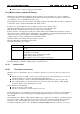
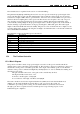
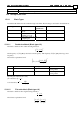
Unit mode Control algorithm
1 Open loop
2 Speed control
3 Micro Stepper
4 Position, dual feedback source.
One sensor serves for commutation and speed control, the other sensor serves
for load position control.
5 Position, single feedback source
Table 15-1 – Unit Mode Values and Definitions
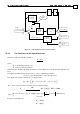
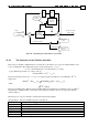
In the basic level of the speed controller, the control algorithm is the traditional PI (Proportional-
Integral). In the basic level of the position controller, the control algorithm is an internal PI speed
loop and an external position loop using a simple gain for the controller, this structure is known as
cascaded loop.
Few hours of playing will suffice for a technician to percept how the modification of the P,I and gain
controller parameters affect the performance of the motor speed loop and position loop.
Life with the above control structures becomes hard as the control requirements become tough.
For this reason, the algorithms are extended to include
1. An high-order filter operating in series with the PI controller, with blocks of the following
types:
Notch filters for notching resonance.
Low pass filters for attenuating very high frequency resonance and decreasing
sensor’s noise.
Lead-lag element, an extra element that helps tradeoff margins versus bandwidth.
2. A continuous scheduling algorithm, which modifies the PI algorithm and some of the
advanced filter parameters as a function of the closed loop operating point.
An advanced user may tune the various filter blocks, but this is not as simple as tuning the PI and the
simple gain. The gain scheduling is programmed by the auto-tuner, although an extremely advanced
user may program it manually.
The following table lists the parameters of the algorithms in this section. Please refer the Command
Reference Manual for the details.
UM Unit Mode. This parameter determines the type of control algorithm to use –
speed, dual-position, or open loop
KP[N] N=2: Inner speed loop proportional gain.