
User's Manual


HARSFEN0602
For more details about gain scheduling, refer the section " The Gain-Scheduling Algorithm".
15.4.2 User Interface
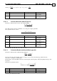
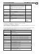
The parameters defined by an array of long integer values set by the KV command.
If KV[0]=0, high order filter is not used and the vector is ignored.
If KV[0] is not zero, the KV[2]..KV[n] defines the filter structure, where KV[1]=n, is the last index used.
Anyway n <= 100.
The filter consists of a number of blocks. It is possible to configure a filter flexible by user interface
command KV, i.e. to define the list of blocks of given types.
KV[0]=100
KV[1]=Filter_Length (last index of KV used)
Filter_structure
{
Block1{
KV[2] =Block_type
KV[3]… =Block_parameter_list
}
Block2{
}
…
Block_Last
{
KV[n]=Block_type=0
}
}
KV[last-2]=0 (reserved)
KV[last-1]=0 (reserved)
KV[last]=-1 – terminator of list
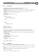
Each block is represented as a list of parameters. The first parameter in each block is the block type,
represented by one KV array element; the block type defines the length of the block parameter list and the
meaning of every parameter.
Other parameters of a block are float values. Every float value x is represented by a pair of KV elements
(Man, Exp) so that
X = Man*exp(Exp),
-2^31 <= Man <= 2^31-1,
-1000 <= Exp <= 32
The following formulae give the appropriate values:
If X=0 the Exp =-1000
If X>0 then
Exp =
floor(log2(X))-30;
If X <0
Exp = ceil(log2(-X))-31;
Man = floor(X / 2^Exp)
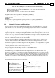
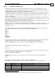
15.4.2.1 An Example
Consisted a filter made of one 2nd-order block and one 1st-order block.
The second order block is a notch filter with 300Hz notch frequency and damping of 0.14. The sample time
is
400 us. The discrete equivalent of the filter is parameterized by k1 = 0.4038, k2=0.3447, k3= -0.7414, k4=
0.4900
The second block is simple pole with frequency 400 Hz. It may be represented by
p=0.3659, q = 1-p =0.6341
The KV parameters vector is be programmed as follow: