
User Guide


9
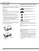
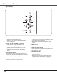
Part Names and Functions
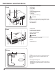
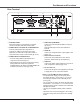
Rear Terminal
⑦ AUDIO IN
Connect the audio output signal from computer or
video equipment to this jack (pp.14-16).
⑤ VIDEO IN
Connect the composite video output signal to this
jack (p.15).
② COMPUTER IN 1 /S-VIDEO IN / COMPONENT IN
Connect analog RGB output signal from a
computer, S-VIDEO output signal from video
equipment, or RGB scart 21-pin video output or
component video output to this terminal (pp.14-16).
④ AUDIO OUT (VARIABLE)
Connect an external audio amplifier to this jack
(pp.14-16).
This terminal outputs sound from AUDIO IN
terminal.
⑥ LAN Connection Terminal
Connect the LAN cable (refer to the owner’s
manual of “Network Set-up and Operation”).
① CONTROL PORT
When the projector is controlled by a computer,
connect to this jack with serial control cable.
③ COMPUTER IN 2 / MONITOR OUT
– Connect analog RGB output signal from a
computer to this terminal (p.14).
– This terminal can be used to output the incoming
analog RGB and Component signal from
COMPUTER IN 1 /S-VIDEO IN /COMPONENT IN
terminal to the other monitor (pp.14,16).
② ③①
④
⑥
⑦
⑤
⑧
⑧ DC OUT 12V 1.1A
Connect the DC power cord (supplied) to this jack
to supply DC 12V to a document camera.
Notes on using ELMO document cameras;
- The projector can supply 12V DC power to the
document camera "L-1ex/TT-02RX" or "L-1n/TT-02s"
with setting to Network mode of Standby mode
menu. (p.51)
- Do not connect any other document cameras other
than ELMO "L-1ex/TT-02RX" or "L-1n/TT-02s" with the
supplied VGA/DC power combined cord. Otherwise
damages may result.
- Use only the supplied VGA/DC power combined
cord.
- When DC OUT 12V jack is plugged in, the cooling
fans are running even if the projector is in standby
mode.