6-ch Digital Hard Disk Recorder EMR-16 Instruction Manual
Table of Contents Introduction .................................................................................................................................1 Before Use ..................................................................................................................................5 Installation ..............................................................................................................................5 Use Environment ..................................................
Stop Copying ................................................................................................................... 41 Image File Format Copied to USB Media ....................................................................... 41 Image File Format Copied to DVD .................................................................................. 41 WEB Server Function ............................................................................................................... 42 Functions ....
Specifications ............................................................................................................................95 Appendix ...................................................................................................................................99 Recording Time Table ..........................................................................................................99 JPEG Display Software: “Resize Viewer” ..........................................................
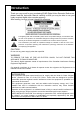
Introduction Thank you very much for your purchasing ELMO Digital Video Recorder. Before use, please read this Instruction Manual carefully so that you may be able to use your newly acquired digital video recorder properly. After reading, be sure to keep it handy for reference.
IMPORTANT SAFETY INSTRUCTIONS 1. 2. 3. 4. 5. 6. 7. 8. 9. 10. 11. 12. 13. 14. 15. 16. 17. Read these instructions. Keep these instructions. Heed all warnings. Follow all instructions. Do not use this apparatus near water. Clean only with dry cloth. Do not block any ventilation openings. Install in accordance with the manufacturer's instructions. Do not install near any heat sources such as radiators, heat registers, stoves or other apparatus (including amplifiers) that produce heat.
PRECAUTIONS - Refer all work related to the installation of these products to qualified service personnel or system installers. - Do not operate the appliances beyond their specified temperature, humidity, or power source ratings. Use the appliance at temperatures within +5 °C - +40 °C (41 °F - 104 °F) and humidity below 80 %. The input power source for this appliance is 120 V AC 60 Hz. Performance and lifetime of hard disk drives are easily affected by heat (used at high temperature) characteristically.
WARNING Handling the cord on this product or cords associated with accessories sold with this product, will expose you to lead, a chemical known to the State of California to cause birth defects or other reproductive harm. Wash hands after handling.
Before Use Below are the reminders you definitely need to know before using the equipment. I nstallation Use Environment y Install the equipment in the environment at temperatures within 5 to 40° and humidity between 30 and 80% (where no due condensation) y When changing the place of installation, be sure to turn off the main power and pull off the power plug from the outlet. y Do not install at places exposed to dust, oily, smoke, steam, or direct sunlight.
Other Cautions Recording Medium (Hard Disk) and Radiating Fan y The hard disk and radiating fan installed inside the equipment are expendables. y When replacing, consult the reseller of your purchase. (Service is chargeable even during the warranty) y A reference life of the hard disk is about 3 years for replacement.
Features ■ High Quality Digital Video and Sound Recording Compared to the conventional VTR using tape recording, digital recording onto a hard disk enables recording of higher quality video and sound data. Unlike tape recording, rewinding or cuing takes very little time.. The recording pixel size is 720×240 per video image. Highly recognized Motion-JPEG is adopted for the data compression method during video recording.
■ Capable of Remote Monitoring Via Network Ethernet terminal is provided as standard equipment enabling connection with networks. By accessing the Web server installed in the equipment via multi-purpose browser from other hosts on the same network, it is able to operate various functions such as distribution of live feeds from the cameras, search or playback of recorded video, remote control or setup of the equipment, etc.
Names and Functions Below are the names and functions of each control on this equipment: Front Face ① ⑦ ② ⑧ ③ ④ ⑤ ⑥ No. Name POWER Key ① ② ③ Description When pushing the POWER switch while recording, playback or live feed display, the screen display of Monitor 1, buzzer, and each indicator will be turned OFF. When pushing the POWER switch during recording, the recording operation is continued though the screen display is turned off. The screen is displayed when pushing the POWER switch again.
No. Name UP Key ④ DOWN Key SEARCH Key Description Increase the setup value Decrease the setup value Used for search of recorded video data. Pushing this key shows Search screen When operation is possible, lamp on the key lights up. Recording Key( ) Starts or stops manual recording. Pushing Recording Key starts manual recording, and pushing it again / stops the manual recording. Recording Stop Key Lamp on the key lights up while manual recording in progress.
Back Face ① ② ⑪ LOOP THROUGH ③ ④ ⑤ ⑥ No. ① Names POWER Switch ② VIDEO IN ③ AC Inlet ④ LOOP THROUGH ⑤ MONITOR OUT 1 MONITOR OUT 2 ⑥ AUDIO IN AUDIO OUT RS-485 Terminal Block RS-485 Termination Switch Ethernet Terminal ⑦ ⑧ ⑨ ⑩ DISK ARRAY CONTROL ⑪ DISK ARRAY 1/2 ⑫ ALARM Terminal Block GND ⑬ ⑦ ⑧ ⑨ ⑩ ⑫ ⑬ Description Turns the power of this equipment on and off. Pushing toward the right turns the power ON and toward the left turns OFF. Video input connectors for Channels ① ~ ⑯.
Connection Below are the instructions on how to connect the equipment with other equipment: Caution y When connecting this equipment with other equipment, be sure to turn off the power of all equipment to be connected.
Example of Connection with VP Power Unit (VC90P, etc) VP Multiple Camera BNC-BNC Coaxial Cable 1 To Camera Input Terminal 16 VP Power Unit BNC-BNC Coaxial Cable To Video Input Connector LOOP THROUGH To Sound Output Terminal BNC-BNC Coaxial Cable To Video Input Terminal To Video Input Terminal To Sound Input Terminal Color Monitor TV - 13 -
Example of Connection with Alarm Devices LOOP THROUGH Control Equipment Lights, etc ■ Connection with Sensor A sensor can be connected to the terminal block on the back as input from alarm signal. Use no-voltage, normally open output type Terminal Specification Input / Output Terminal ・Alarm input Input / Output Terminal Circuit LVC245 Signal Specification VCC (+3.
Example of Connection with External Control Equipment ■ Mouse Connect a mouse to the USB Port (MOUSE) on the front of the equipment. ■ Ethernet - When connecting via HUB: Host HUB LO O P T HR O UG H Ethernet Straight Cable Host Connect the Ethernet Terminal of this equipment with the HUB port. Use other than MDI Port of the HUB. Use Ethernet straight cable (UTP Category 5) available for general use.
Example of Connection with External Storage Media ■ USB By connecting USB media to USB Port (ARCHIVE) on the equipment front, video or equipment setup data can be stored onto it. Caution y USB media to be used must be USB-compliant USB mass storage compatible, with power consumption under 500mA. (However, it does not guarantee connection with all equipment) For more information, contact the shop staff. y The media to be used with this equipment needs to be formatted in FAT12/FAT16.
Example of Connection with Expansion Hard Disk Unit See Instruction Manual of the expansion hard disk unit EMR-ESU for more details. The display indication of the hard disk information on this equipment is as follows: BUS Indication Installed Primary (IDE0) HDD-A Installed Secondary (IDE1) HDD-B No.
How To Use Below are basic explanations for using this equipment: Starting Up 1. 2. 3. Connect the provided power cable and each device appropriately. Turn the POWER Switch on the back face “ON.” The screen shows the System Check display, and the hard disk Connection Check begins. During the Connection Check, the “POWER” key flickers. EMR-16 Ver 1.00 0009 SYSTEM INITIALIZING. → ●●●●● After the System Check finishes, the “POWER” key changes to lighting mode, and a live feed is shown.
Viewing iewing Live Feeds Below explains how to show live feeds from connected cameras full screen. Split screen display is also possible by key control. Caution y Channels whose number begins with “L” shows live feed. Display arrangement can be done in “LAYOUT” setting. y “ELMO” logo is displayed when the video image output is set to OFF in the Monitor Output Setup or when the screen is set to the playback mode. Screen Display While Showing Live Feeds ① L1 SAT JAN/01/05 00:00:00 ② 1 ③ No.
Switching Cameras Push the camera selection key of your choice. ⇒ The live feed from the selected camera will be displayed on the monitor screen. L1 Camera Selection Key “1” L3 Camera Selection Key “3” Display in Split Screen Footages from multiple cameras are displayed in split screen mode. 7 split screen patterns are possible as shown below: 16-split screen mode displays only the camera numbers, not the names thereof.
1. Push the “MENU” or “SCRN DIV” key. Or, right-click on it with the mouse. ⇒ The Operation / Setup Menu will be displayed. L 1 PL AY REVERSE SE TUP SEARCH D I V L A YOU T DA TA COPY SEQUENCE CAMERA REMA I N T I ME 0 0 0 0 0D0 0H 1 NOTE: * “LAYOUT on the Operation / Setup Menu is not displayed unless LAYOUT MODE of System Setup is set to ACTIVE. 2. Using the “3” and “11” keys, move the cursor to “DIV” and push the “7” key. Or click on “DIV.” ⇒ The Screen Division Setup screen will be displayed.
Automatic Sequence Display 1. 2. Pushing the “SEQ DISP” key automatically changes the monitor display according to the setup. * As for the setup method, see “Automatic Sequence Setup” under “Screen Display Setup” (→P.73) Changing the screen to another mode finishes the Automatic Sequence. PTZ Camera Control This display function is possible for Monitor 1 in the single screen and the live feed display mode. It is not available for Monitor 2.
y Following is how to select and operate from the Operating Menu screen: 1. Push the “MENU” key. Or, click the right button on the mouse. ⇒ The Operation / Setup Menu will be displayed. L 1 P L AY REVERSE SETUP SEARCH D I V L A YOU T DATA COPY SEQUENCE CAMERA REMA I N T I ME 0 0 0 0 0D0 0H 1 NOTE: * “LAYOUT” on the Operation / Setup Menu is not displayed unless LAYOUT MODE of System Setup is set to ACTIVE. 2. Using “3” and “11” keys, move the cursor to the “CAMERA” button and push “7” key.
2X Digital Zoom Display This display function is possible for Monitor 1 in full screen display mode. It is not available for Monitor 2. 1. 2. 3. Click “X2” button in the Camera Control screen. ⇒ 2X zoom image will be shown. Using the mouse, or “3,” “6,” “8,” and “11” keys, the zoomed section can be moved. For ending Zoom mode, push the “CAM” key once again. Viewing Live Feeds from Monitor 2 Monitor 2 shows live feeds at all times. 1. 2. Push the “MON 2” key.
Recording cording This operation records live feeds onto hard disk. Two types of recording modes are available; Manual Recording and Automatic Recording. y Manual Recording: Recording begins when the “Recording” key is pushed. y Automatic Recording: Recording begins automatically according to the schedule (continue, alarm input, and motion) set up for each camera. Screen Display During Recording ① L1 SAT JAN/01/05 00:00:00 ② ③ ●AUTO ♪ ⇒ MIRROR ④ No. ① Names Channel No.
Manual Recording 1. 2. Pushing the “Recording” key once again stops the recording. Push the “Recording” key during live feed display or playback. ⇒ “RECORDING” indicator lights up and manual recording begins according to the recording setup. Note Pushing the “Recording” key during automatic recording switches to manual recording mode. When the automatic recording conditions (continue, alarm, or motion) happen during manual recording, these do not start recording.
Playback ayback Below explains how to play back recorded video. Playback is also possible during recording. Playback is possible only on Monitor 1. Monitor 2 is not capable of playback. Caution y Channel whose number begins with “PB” shows playback video. Display arrangement can be done in “LAYOUT” setting. y Channel that shows live feed is in “live feed mode” and doesn’t playback video. y To start playback video,please set the screen to playback video in LAYOUT setup.
Recording Mode Indication ⑦ Indicates hard disk recording mode Nothing displayed: Extended recording MIRROR: Mirroring recording Recording mode is set up using the hard disk formatting method. (→ P.89 “How to Format Hard Disk”) Note The display location of ② above or the indications for ④ to ⑦ can be undisplayed by changing the OSD Display Setup (→ P.70) Playback/Stop Playback 1. 2. During ELMO log is displayed in playback video screen, push the “ (Playback)” key or (Reverse playback)”key.
Note y Playback begins from the point where the last playback or backward playback stopped. When the playback continues to the beginning or the end of the recorded data, playback stops and returns to “E L M O” logo displayed. y When the power is turned on or the point of the last playback or backward playback has been overwritten, playback starts from the oldest point and backward playback starts from the newest point. While overwrite recording is in progress, playback cannot be conducted.
Playback at Fast Speed y Using Shuttle Dial While playback is paused, turning the Shuttle Dial in REW(backward) or FF (forward) direction, still images are played back at a fast speed. Display in Split Screen Footages from multiple cameras are displayed on monitor in split screen. The control method is the same as “Display in Split Screen” under “Viewing Live feed.” (See P.
How to Use LAYOUT Function During split screen display, live feed and playback video can be displayed at the same time. This function is available during split screen display on Monitor 1. Note y “LAYOUT” is not displayed as LAYOUT MODE is set to INACTIVE when the product is shipped from the plant. Set LAYOUT MODE of System Setup to ACTIVE to use the LAYOUT function.(→See P.79) Caution y A live feed from one camera cannot be displayed on multiple split screens. 1. Push the “MENU” key.
3. Using the “3,” “6,” “8,” and “11” keys, move the cursor sor to the Camera No. where the display is to be changed, and push the “7” key. Or click on the image where the display is to be changed. Cursor PB1 PB2 PB3 PB4 4. Using the “3,” “6,” “8,” and “11” keys, move the cursor to the Camera No. desired to be displayed and push the “7” key. Or click on the No. desired to be displayed. LIVE indicates live feed and PLAY indicates playback video.
Finishing LAYOUT Function 1. Push the “MENU” key, or right-click on it using the mouse. ⇒LAYOUT Setting mode (End process) screen is displayed. L 5 P B 2 BACK EX I T PB 3 2. P B 4 Using the “3,” and “11” keys, move the cursor to the “EXIT” button and select it by pushing the “7” key. Or, click on the “EXIT” button. ⇒LAYOUT function is finished and split screens are displayed on the monitor. * Selecting the “CANCEL” tab displays Camera Selection Menu.
Search and Playback Recorded Video Below explains how to search and play back recorded video. Note y After LOGIN to the recorded video search screen, the LOGIN status stays until “LOGOUT” is pressed. User authentication is not required if you search recorded video again under the LOGIN status. y If you have returned to the live screen without logging out, you will be automatically logged out when the search login time (the value set at factory shipment is 5 minutes) has passed.
5. Using the “3,” “6,” “8,” and “11” keys, move the cursor to the “OK” button and select by pushing the “7” key. Or, click on the “OK” button. ⇒ The Record Search Item Entry screen will be displayed.
END DATE is displayed. Otherwise the video of the oldest event between START DATE and END DATE is displayed.
7. 8. Push the “SEARCH” button. Using the “3,” “6,” “8,” and “11” keys, move the cursor to the “SEARCH” button and select it by pushing the “7” key. Or, click on the “SEARCH” button. ⇒ Search begins on the specified criteria, and paused recording image, preceding and nearest the specified time, is displayed.When no recording data is found for the searh criteria, “NO HIT!” sign is indicated above the SEARCH key of the screen.
Copy Function This function transfers recorded data on HDD to USB media connected to ARCHIVE port.This function transfers data to USB media connected to USB2 Port (ARCHIVE) or to DVD. Caution y USB Connect USB media to the ARCHIVE port. Only mass storage class is compatible. The used media must be formatted in FAT12/FAT16 and the compatible interface must be USB2.0/1.1. The copying function copies an easy viewer application (VIEWER.EXE) and the intended video data. y DVD Data can be output to DVD-R/DVD-RW.
3. Using the “3” and “11” keys, move the cursor to the “DATA COPY” button and push the”7” key. Or, click on the “DATA COPY” button. ⇒ The User Name Entry Screen will be displayed. LOGIN USER NAME 0 A K U a k u 1 B L V b l v 2 C M W c m w OK 3 D N X d n x 4 E O Y e o y 5 F P Z f p z 6 G Q 7 H R 8 I S 9 J T g q h r i s j t BS CANCEL 4. Enter the user name. Using the “3,” “6,” “8,” and “11” keys, move the cursor to the desired letters and select by pushing the “7” key.
7. Using the “3,” “6,” “8,” and “11” keys, move the cursor to the “USB” or “DVD” button and select by pushing the “7” key. Or, click on the “USB” or “DVD” button. ⇒ The Data Copy Item Entry screen will be displayed.
Stop Copying 1. 2. Press the ”MENU” key during transfer. Or, right-click the mouse. ⇒The data copy end screen is displayed. Pushing the “Stop” key, during data transfer displays Transfer Cancellation Confirmation message. Move the cursor to “COPY STOP” with the “3”, “6”, “8” or “11” key and finalize with the “7” key. Or, click “COPY STOP.” ⇒The transfer stop confirmation message is displayed.
WEB Server Function Below explains how to use EMR-16 through a WEB browser.
Login/Logout 1. When accessing the equipment’s contents for the first time, the certification screen appears. Authentication USER PASSWORD LOG IN 2. Enter the User Name and Password, and click on the “LOG IN” button. The password entered is displayed by the “●” mark. There are two types of certification account; general account and setup account. - General account (User level): possible to browse only live feed distribution - Setup account (ADMIN level): possible to operate all functions 3.
Caution y Entry of wrong User Names or Password does not change the screen display but continues to show the certification screen. In case the maximum number (3 accounts) of clients are accessing, the screen shows an message as shown below and the operation is discontinued. y Up to one setup account or up to three general account can login at the same time, and therefore, if accessing the equipment while other client has already logged in, the same message is displayed.
LIVE FEED Through communication with EMR-16, live feeds are distributed. Default display setup is 16-split screen mode. CAMERA3 CAMERA4 ▲ ▲ ▼ ▼ CAMERA2 CAMERA1 CAMERA5 CAMERA6 CAMERA7 CAMERA8 CAMERA9 CAMERA10 CAMERA11 CAMERA12 ▼ ▼ REC START REC STOP CAMERA13 1 2 3 4 CAMERA14 5 6 7 8 CAMERA16 CAMERA15 9 10 11 12 13 14 15 16 4SEG A 4SEG B 4SEG C 4SEG D 9SEG A 9SEG B 16SEG y Changing Split Screen Mode Using the camera switch keys, displaying cameras can be changed: Camera No.
PLAYBACK Through communication with EMR-16, live feed and playback video can be displayed. This operation is possible only by access in the setup account The last played video is displayed in a paused image by default, but immediately after the power of the equipment is turned on or when recorded data is not available, a black screen is displayed.
◀◀ ▶▶ ◀╽╽ ╽╽▶ ╽◀◀ ▶▶╽ Fast backward playback (2× →4× →8×) Fast forward playback (2× →4× →8×) Frame by frame backward playback while pausing Pause Frame by frame forward playback while pausing A pausing display of the oldest video image A pausing display of the newest video image Note y When the position of the oldest or the newest recorded data is reached during forward or backward playback, a pausing display of the final video image is shown.
y Duplex Display During playback in split screen mode, one of the split screens can be changed to live feed thus displaying playback video and live feed at the same time. Right-click on the screens to open the pop-up menu. Camera 1 Camera 2 Camera 1 Camera 2 Camera 3 Camera 3 Camera 4 Right-click to open the pop-up menu. Camera 14 Camera 15 Camera 16 Cancel Selecting one out of Cameras 1~16 on the pop-up menu, the screen showing the pop-up menu is changed to the selected live feed.
MENU The Menu setup of the equipment can be viewed and changed. This function is available only when login with a setup account. The Menu below is displayed. By clicking on one of the buttons, the setup screen is displayed.
Warning - Security Do you trust the applet with a signature provided from "XXXX"? Reliability of the issuer has been verified by "XXXX." This security certificate has been issued by an unreliable group. This security certificate has not been expired and is still valid. Caution: "XXXX" Declares the contents herein are safe. Approve the contents only when the declaring "XXXX" can be trusted. Details Yes (Y) No (N) * Some versions of Java might show a different message from the above.
E-Mail Function In the event of recording start due to alarm input or motion detect or internal alarm generation, e-mail is sent containing the messages shown below: See “E-mail Setup” (→P.
How To Set Up Below are explanations of the contents and method of setup using the Menu screen. H ow to Start and Finish Menu Mode 1. During live feed display, push the “MENU” key. Or, right click on it with a mouse. ⇒ The Operation / Setup Menu will be displayed. L 1 PL AY REVERSE SE TUP SEARCH D I V L A YOU T DA TA COPY SEQUENCE CAMERA REMA I N T I ME 0 0 0 0 0D0 0H 1 2. Using the “3” and “11”keys, move the cursor to the “MENU” button and select it by pushing the”7” key.
4. Using the “3,” “6,” “8,” and “11” keys, move the cursor to the “OK” button and select by pushing the “7” key. Or, click on the “OK” button. ⇒ The Password Entry screen will be displayed. LOGIN USER NAME ADMIN PASSWORD ***** 0 A K U a k u 1 B L V b l v 2 C M W c m w OK 3 D N X d n x 4 E O Y e o y 5 F P Z f p z BACK 6 G Q 7 H R 8 I S 9 J T g q h r i s j t BS CANCEL 5. Enter the password.
Operation of Menu Screen Below are explanations of basic operation of each screen under the Menu mode Example) Recording Conditions setup REC CONDITION ALL CAM CAM CAM CAM CAM CAMERAS 1 2 3 4 5 SETUP REC REC RATE YES 2PPS YES 60PPS YES 2PPS YES 4PPS YES 15PPS NO - 2.
List of Menu Functions The settings shown in ( ) indicate factory default setup. Menu item Items Screen Display Setup Recording Setup OVERWRITE Recording Conditions Setup REC (For each camera) REC RATE (For each camera) Settings Ref. page YES/NO (NO) YES/NO (YES for all cameras) 60PPS, 30PPS, 15PPS, 10PPS, 7.5PPS, 5PPS, 4PPS, 3PPS, 2PPS, 1PPS (7.
Menu item Items Settings RECORD TIME HDD MODE DATE TIME DATE OSD POSITION Monitor output setup Auto sequence setup MONITOR1 CAM NAME MONITOR2 CAM NAME MONITOR1 (For each camera) MONITOR2 (For each camera) MONITOR1 MONITOR2 Camera Name Setup (For each camera) IP ADDRESS Network SUBNET MASK Setup DEFAULT GATEWAY PRIMARY DNS SERVER SECONDARY DNS SERVER WEB PORT NUMBER LIVE DELIVERY IMAGE TRANSFER RATE E-mail Setup SOURCE ADDRESS DESTINATION ADR1 DESTINATION ADR2 DESTINATION ADR3 DESTINATION ADR4 SMTP S
System Setup HD REMAINING TIME BUZZER ALARM OUTPUT ALARM OUTPUT TIME Control Camera Setup User Setup Log Viewer TYPE 0~999 hours (1 hour) EFFECT/NO EFFECT (EFFECT) DURING ALARM REC INTERNAL ALARM LEVEL WARNING ALL (ALL) DURING ALARM REC 1 SEC (DURING ALARM REC) PTC-200C / PELCO-D / OTHER (OTHER) 80 CAM ID ADMIN1-4 Within 10 letters (1: ELMO, others: blank) ADMIN PASS1-4 Within 10 letters (1: ELMO, others: blank) USER1-16 Within 10 letters (All blank) USER PASS 1-16 Within 10 letters (All bkank) REC
Equipment Maintenance TIME SETUP HDD RESET SETUP RESET LOG RESET EXPORT SETTING IMPORT SETTING DAYLIGHT SAVINGS TIME BEGIN END NTP SERVER DOMAIN TIME ZONE AUTO LOGOUT TIME 2000/1/1~2099/12/31 (2005/1/1 00:00:00) Cannot be set for dates not in existence such as 2/31 Formats the hard disk (Extended mode) Rests the setup Rests the log Writes the setup on a connected media Reads the setup from a connected media ON/OFF (ON) Month / Week Day Time (MAR 2ND SUN 2:00 AM) Month / Week Day Time (NOV 1ST SUN 2:00 A
Main menu screen Display setting screens from the main menu. Set the search login time of AUTO LOGOUT TIME. NOTE When you access this unit with a WEB browser, set AUTO LOGOUT TIME on the SYSTEM SETUP screen.
Recording Setup Below are instructions for recording setup: REC SETUP REC CONDTION SETUP ENTER SCHEDULE SETUP ENTER CONCURRENT SETUP ENTER HOLIDAY SETUP ENTER MOTION SETUP ENTER OVERWRITE YES MENU Items REC CONDITION SETUP SCHEDULE SETUP CONCURRENT SETUP HOLIDAY SETUP MOTION SETUP OVERWRITE MENU Settings Displays the recording setup screen (→P.61) Displays the schedule setup screen (→P.63) Displays the concurrent recording camera (→P.65) Displays the holiday setup screen (→P.
Recording Conditions Setup Recording conditions such as image quality or intervals can be set up for each camera.
・ESTIMATED REC RATE Displays a reference remaining recordable time based on a calculation of the current recording setups and the hard disk free spaces. ■ Setup of Image Quality The “File Size” indicates the size of data after compression, and the larger the size is the image quality is finer, closer to the original video footage. IMAGE 1 indicates the highest image quality although the recording time is shorter than other lower settings. IMAGE 4 conversely is the lowest yet suitable for Extended recording.
Recording Schedule Setup Automatic recording conditions can be set up for each camera.
* In case “ALARM & MOTION” is selected, complete the setup for Concurrent Recording Camera also. (→P65) Items PREV NEXT MENU Settings Returns to the Recording Setup Screen (→P.61) Displays the Concurrent Recording Camera Setup Screen(→P.
Concurrent Recording Camera Setup How to conduct setup for concurrent recording operation upon alarm or motion detection.
Holiday Setup Specific dates when Automatic recording is conducted can be set up. The specific dates correspond to the dates indicated by the “HOL” sign on the Recording Schedule Screen. A maximum of 80 days can be set up for one year.
Motion Setup How to conduct Motion Detect Setup. 1. Select “ENTER” button of the intended camera. MOTION CAM CAM CAM CAM CAM CAM CAM CAM CAM CAM CAM CAM CAM CAM CAM CAM SETUP 1 1 1 1 1 1 1 1 2 3 4 5 6 7 8 9 0 1 2 3 4 5 6 ENTER ENTER ENTER ENTER ENTER ENTER ENTER ENTER ENTER ENTER ENTER ENTER ENTER ENTER ENTER ENTER MENU ⇒ The Motion Setup Screen will be displayed. Camera No.
・ Using a mouse 1) Click on the intended area for motion setup. Each click changes between ON and OFF. Motion Detect ON: Green color Motion Detect OFF: No color 2) Right click of the mouse shows the menu for sensitivity setup of the selected area. ENTER BACK ・・・Setup finished CANCEL ・・・Returns to the Motion Setup Screen SENSE1 ・・・Returns to the Motion Screen Selection Screen SENSE2 SENSE3 SENSE4 ・・・Sensitivity 1~5 SENSE5 3) Click on the “ENTER” button.
Screen Display Setup Below shows how to set up screen display. D I S P L A Y O S D S E T U P S E T U P MON I T OR E N T E R OU T P U T S E T U P E N T E R A U T O S E QU E N C E S E T U P ( M O N 1 ) E N T E R A U T O S E QU E N C E S E T U P ( M O N 2 ) E N T E R C AME R A N AME S E T U P E N T E R MON I T OR 1 I N I T . MOD E 9 S E G A MON I T OR 2 I N I T .
OSD Display Setup Below are instructions on how to set up the screen display using playback or recording.
Items MONITOR1 CAM NAME MONITOR2 CAM NAME MENU Settings DOWN: Center bottom LEFT UP: Left top LEFT DOWN: Left bottom RIGHT UP: Right top RIGHT DOWN: Right bottom Enable or disable the display of camera names OFF: Disables display NAME: Enables display of camera names NUM: Enables display of camera No.
Monitor Output Setup This is to set up whether to display the live feeds from each camera on Monitor 1 or 2. During playback, all cameras’ recorded video is displayed regardless of the setup entered herein.
Automatic Sequence Setup This menu sets up the screen display operation when pushing the “SEQ DISP” key. (In case the sequence setup is changed during automatic sequence in operation, the change setup is activated after the current sequence operation is finished.
Camera Name Setup This is to set up then names of each camera. Camera No.
Network Setup This sets up parameters necessary for LAN connection.
E-mail Setup This is to establish the e-mail setting to be conducted in the event of an alarm input or malfunction.
[Setup Procedure of Address, User Name and Password] Screen display example) Source Address S O U R C E A D D R E S S t e s t 0 A K U a k u ! + ? O K 1. 2. 1 B L V b l v " , @ 2 C M W c m w # ^ 3 D N X d n x $ . _ 4 E O Y e o y % / ` 5 F P Z f p z & : { 6 G Q 7 H R 8 I S 9 J T g q h r i s j t ' ; | ( < } ) = ~ * > B S C A N C E L Using the “3,” “6,” “8,” and “11” keys, move the cursor to the letters to be entered and select by pushing the “7” key.
Sending Condition Setup This is to set up whether to send e-mail in the event of an internal alarm, recording start due to alarm input or motion detection.
System Setup SYSTEM SETUP HD REMAINING TIME BUZZER ALARM OUTPUT DURING ALARM REC INTERNAL ALARM LEVEL WARNING ALARM OUTPUT TIME CAMERA SETUP USER SETTING PLAY DISK LAYOUT MODE 0 HOUR EFFECT ON OFF OFF DURING REC ENTER ENTER ALL INACTIVE MENU Items HD REMAINING TIME BUZZER ALARM OUTPUT DURING ALARM REC INTERNAL ALARM LEVEL WARNING ALARM OUTPUT TIME CONTROL CAMERA USER SETTING PLAY DISK LAYOUT MODE MENU Settings Sets the remaining recording time under which the “HDD” indicator lights up in orange in
Control Camera Setup Screen This is to select the camera to be controlled by RS-485.
User Setup From this screen, User Setup and registration can be conducted. Administrator user cannot conduct this Setup.
1. Using the “3,” “6,” “8,” and “11” keys, move the cursor to the “ENTER” button of the password to be changed and select by pushing the “7” key. Or, click on the “ENTER” button. ⇒ The Password Entry Screen will be displayed. PASS WORD ***** REWRITE PASSWORD ***** 0 A K U a k u 1 B L V b l v 2 C M W c m w OK 2. 3. 3 D N X d n x 4 E O Y e o y 5 F P Z f p z 6 G Q 7 H R 8 I S 9 J T g q h r i s j t BS CANCEL Enter the password.
Log Display Log Display has the following items: y REC LOG: Log of dates and times when recording started and ended y ERROR LOG: Log of times and types of error occurrence y STARTUP LOG: Log of times when the equipment was turned on or restored from power outage y USER LOG: Log of USER operations described by user names and menu names LOG VIEWER REC LOG ERROR LOG STARTUP LOG USER LOG ENTER ENTER ENTER ENTER MENU Recording Log This displays the dates and times of recording start and end from the latest lo
Error Log This displays the dates and times when errors occurred with the latest log entry at the top. This log records up to 100 entries after which point the oldest ones are deleted in order.
Startup Log This log records the dates and times when the power was turned or the equipment was restored from power outage, and displays the latest log entry at the top. This log records up to 100 entries after which point the oldest ones are deleted in order.
User Log This log records the operations by USERS and displays the latest record at the top. This log records up to 200 entries after which point the oldest ones are deleted in order.
Items Setting value Indications POP3 SERVER: POP3 server setting input screen SUBMIT SETUP: Sending condition setting screen SYSTEM SETUP: System setting screen CAMERA SETUP: Control camera setting screen USER SETUP: User setting screen USER ENTRY: User setting input screen PASSWORD: Password setting input screen USER CTRL SET: User control setting screen LOG VIEWER: Log menu screen REC LOG: Log screen (recording) ERROR LOG: Log screen (error) START UP LOG: Log screen (start) USER LOG: Log screen (operati
Equipment Maintenance This setup conducts the resetting of log records or formatting of hard disks. MAINTENANCE TIME SETUP HDD RESET SETUP RESET LOG RESET EXPORT SETTING IMPORT SETTING DAYLIGHT SAVINGS TIME BIGIN END NTP SERVER DOMAIN TIME ZONE 2005Y 1M 1D 0H 0M 0S ENTER ENTER ENTER ENTER ENTER ON APR 1ST SUN 2:00 OCT LAST SUN 2:00 ntp.
Writing Method 1. When selecting “SETUP RESET,” “LOG RESET,” “EXPORT SETTING,” or “IMPORT SETTING,” the confirmation screen for executing the selected maintenance is displayed. MA I N T ENANCE 2. E X E C U T E ? Y E S N O Use the “6” and “8” keys to move the cursor to the “YES” button, and select it with the “7” key. When using a mouse, click on the “YES” button. ⇒ The selected maintenance operation is executed. * For cancelling the selected maintenance, select “NO.
Below is the data writing order in each disk mode in the hard disk setup: Extended (Long) recording HDD-A → HDD-B → HDD-A → ・・・ HDD-C → HDD-D → HDD-E → HDD-F → Mirroring recording 1 (Mirroring for Installed HDD, Expanded HDD Unit 1 and Expanded HDD Unit 2) HDD-A ⇔ HDD-B → HDD-C ⇔ HDD-D → HDD-E ⇔ HDD-F → HDD-A ⇔ HDD-B → ・・・ Mirroring recording 2 (Mirroring for Expanded HDD Unit 1 and Expanded HDD Unit 2) HDD-C ⇔ HDD-D → HDD-E ⇔ HDD-F → HDD-C ⇔ HDD-D → HDD-E ⇔ HDD-F → ・・・ * In case the hard disk capaci
Operation Under Error Status H ard Disk Error In case an error occurs in hard disks while recording including pre-alarm, the recording is continued using other hard disks regardless of the recording mode. In such a case, the equipment alarm indicator flickers, buzzer sounds (according to setup), alarm is output (according to setup) and error log conducts recording.
Output under Error Status Alarm Output Alarm output setup Alarm recording Alarm output time setup During alarm recording 1 second Internal alarm ― Remaining ― time warning Buzzer Buzzer setup Recording on alarm input and motion Output during recording Output for 1 second after recording start Not influenced Not influenced OFF Recording on alarm input and motion Output during recording Press “STOP” key to stop the buzzer.
Troubleshooting When encountering the situations below, follow the instructions and try the troubleshooting measures provided. In case doing so does not solve the problem, contact the dealer where you purchased the DVR. Phenomenon No screen image Possible Cause Power is not turned on. Power plug is not inserted into the outlet properly. Measures to be taken Start up the equipment. (→P.18) After turning the main power off, insert the power plug all the way, and start up the equipment.
Warranty and Services Warranty The warranty certificate is presented from the dealer. Be sure to check the “name of dealer, purchase date” etc on the certificate, read the warranty descriptions carefully and keep it safely. The duration of warranty of this equipment is 2 years from the date of purchase. The warranty for hard discs is for 1 year from the date of purchase. When requesting repair during warranty period Contact the dealer of your purchase.
Specifications 1. Basic Specifications Items Power Power consumption External dimensions Weight Recommended Installation Service temperature and humidity Accessories Description 120VAC, 60Hz 70W W: 420.5, H :88, D: 368 (mm) Approx. 8.2 kg Indoors, on a flat area (horizontally) 5℃~40℃, 30%~80% Remarks HDD×4 HDD×4 Non-condensing Instruction Manual, AC cable, Warranty, HDD Instruction 2.
3. Function Specifications Items Recording Image processing method Sound processing method Recording medium Manual recording setup Description Encoding method: Motion JPEG Input: 13.5MHz 4:2:2 format 8 bit Pixels: 720×240 pix/field Encoding method: PCM digital Input: 16kHz 8bit monaural 3.5” HDD (IDE) mounted 4 units as normal equipment Recording interval: 10 steps (60, 30, 15, 10, 7.
Screen Display Items Display Operation status display Title display Clock Display Precision Leap year Zoom Function Playback Function Search Function Log Function, Alarm Log Serial RS-485 Network Function Description Text display: 20×6 dots No.
Items Copy Function Security Description Remarks Possible to output recorded video for USB media and DVD are optional. storage media (USB media, DVD) Connecting USB media to the USB port (ARCHIVE) port DVD drive is mounted on the EMR-16 at the user’s option.
Appendix R ecording Time Table * The indications are in units of hours * The recording times are reference in case all cameras have the same recording interval setup * Recording interval units: pps ■ Mirroring Recording Using 4 Units of 250GB HDD 1 camera Without sound recording Rec Interval 1/60 Frames / 1 sec 60 Quality Setup Image Quality 1 35.61 Image Quality 2 47.24 Image Quality 3 70.15 1/30 1/15 1/10 2/15 1/5 1/4 1/3 1/2 1 30 15 10 7.5 5 4 3 2 1 71.23 142.45 284.90 284.90 427.
3 cameras Without sound recording Rec Interval 1/60 Frames / 1 sec 60 Quality Setup Image Quality 1 - Image Quality 2 - Image Quality 3 - Image Quality 4 - 3 cameras 4 cameras - - 5 cameras 2/15 1/5 1/4 1/3 1/2 1 30 15 10 7.5 5 4 3 2 1 237.42 314.94 467.64 907.77 356.13 472.41 701.46 1361.66 712.25 944.82 1402.92 2723.31 - - - - 47.48 71..23 94.97 142.45 178.06 62.99 94.48 125.98 188.96 236.21 93.53 140.29 187.06 280.58 350.73 181.55 272.33 363.11 544.66 680.
5 cameras With sound recording Rec Interval Frames / 1 sec Quality Setup Image Quality 1 Image Quality 2 Image Quality 3 Image Quality 4 6 cameras 1/60 1/30 1/15 1/10 2/15 1/5 1/4 1/3 1/2 1 60 30 15 10 7.5 5 4 3 2 1 - - - - - - - - - - - - 100.64 131.03 187.69 330.69 131.34 169.89 240.50 411.52 190.26 243.66 338.75 555.56 342.94 427.35 566.89 841.
8 cameras Without sound recording Rec Interval 1/60 Frames / 1 sec 60 Quality Setup Image Quality 1 - Image Quality 2 - Image Quality 3 - Image Quality 4 - 8 cameras Quality Setup Image Quality 1 Image Quality 2 Image Quality 3 Image Quality 4 1/10 2/15 1/5 1/4 1/3 1/2 1 30 15 10 7.5 5 4 3 2 1 - - - - - - - - - - - - Quality Setup Image Quality 1 Image Quality 2 Image Quality 3 Image Quality 4 1/60 1/30 1/15 1/10 2/15 1/5 1/4 1/3 1/2 1 60 30 15 10 7.
10 cameras Rec Interval Frames / 1 sec Quality Setup Image Quality 1 Image Quality 2 Image Quality 3 Image Quality 4 11 cameras Rec Interval Frames / 1 sec Quality Setup Image Quality 1 Image Quality 2 Image Quality 3 Image Quality 4 11 cameras Rec Interval Frames / 1 sec Quality Setup Image Quality 1 Image Quality 2 Image Quality 3 Image Quality 4 12 cameras Rec Interval Frames / 1 sec Quality Setup Image Quality 1 Image Quality 2 Image Quality 3 Image Quality 4 12 cameras Rec Interval Frames / 1 sec Quali
13 cameras Rec Interval Frames / 1 sec Quality Setup Image Quality 1 Image Quality 2 Image Quality 3 Image Quality 4 13 cameras Rec Interval Frames / 1 sec Quality Setup Image Quality 1 Image Quality 2 Image Quality 3 Image Quality 4 14 cameras Rec Interval Frames / 1 sec Quality Setup Image Quality 1 Image Quality 2 Image Quality 3 Image Quality 4 14 cameras Rec Interval Frames / 1 sec Quality Setup Image Quality 1 Image Quality 2 Image Quality 3 Image Quality 4 15 cameras Rec Interval Frames / 1 sec Quali
15 cameras Rec Interval Frames / 1 sec Quality Setup Image Quality 1 Image Quality 2 Image Quality 3 Image Quality 4 16 cameras Rec Interval Frames / 1 sec Quality Setup Image Quality 1 Image Quality 2 Image Quality 3 Image Quality 4 16 cameras Rec Interval Frames / 1 sec Quality Setup Image Quality 1 Image Quality 2 Image Quality 3 Image Quality 4 With sound recording 1/60 1/30 1/15 1/10 2/15 1/5 1/4 1/3 1/2 1 60 30 15 10 7.
■ Extended Recording Using 4 Units of 250GB HDD 4 1 camera Without sound recording Rec Interval 1/60 1/30 1/15 1/10 2/15 1/5 1/4 1/3 1/2 1 Frames / 1 sec 60 30 15 10 7.5 5 4 3 2 1 Quality Setup Image Quality 1 71.23 142.45 284.90 427.35 569.80 854.70 1068.38 1424.50 2136.75 4273.50 Image Quality 2 94.48 188.96 377.93 566.89 755.86 1133.79 1417.23 1889.64 2834.47 5668.93 Image Quality 3 140.29 280.58 561.17 841.75 1122.33 1683.50 2104.38 2805.84 4208.75 8417.51 Image Quality 4 272.33 544.66 1089.32 1633.
3 cameras Without sound recording Rec Interval 1/60 Frames / 1 sec 60 Quality Setup Image Quality 1 - Image Quality 2 - Image Quality 3 - Image Quality 4 - 3 cameras 1/30 1/15 1/10 2/15 1/5 1/4 1/3 1/2 1 30 15 10 7.5 5 4 3 2 1 474.83 629.88 935.28 1815.54 712.25 944.82 1402.92 2723.31 1424.50 1889.64 2805.84 5446.62 47.48 94.97 142.45 189.93 62.99 125.98 188.96 251.95 93.53 187.06 280.58 374.11 181.55 363.11 544.66 726.22 284.90 356.13 377.93 472.41 561.17 701.46 1089.32 1361.
5 cameras With sound recording Rec Interval 1/60 Frames / 1 sec 60 Quality Setup Image Quality 1 - Image Quality 2 - Image Quality 3 - Image Quality 4 - 6 cameras 6 cameras - - 1/5 1/4 1/3 1/2 1 30 15 10 7.5 5 4 3 2 1 201.29 262.05 375.38 661.38 262.67 339.79 481.00 823.05 380.52 487.33 677.51 1111.11 685.87 854.70 1133.79 1683.50 - - - - 55.69 82.92 109.74 162.21 73.34 108.93 143.83 211.64 107.35 158.73 208.66 304.41 200.20 292.40 379.87 542.
8 cameras Without sound recording Rec Interval 1/60 Frames / 1 sec 60 Quality Setup 1/30 1/15 1/10 2/15 1/5 1/4 1/3 1/2 1 30 15 10 7.5 5 4 3 2 1 Image Quality 1 - - 35.61 53.42 71.23 106.84 133.55 178.06 267.09 534.19 Image Quality 2 - - 47.24 70.86 94.48 141.72 177.15 236.21 354.31 708.62 Image Quality 3 - - 70.15 105.22 140.29 210.44 263.05 350.73 526.09 1052.19 Image Quality 4 - - 136.17 204.25 272.33 408.504 510.62 680.83 1021.24 2042.
10 cameras With sound recording Rec Interval 1/60 Frames / 1 sec 60 Quality Setup Image Quality 1 - Image Quality 2 - Image Quality 3 - Image Quality 4 - 11 cameras 11 cameras - - 12 cameras 2/15 1/5 1/4 1/3 1/2 1 30 15 10 7.5 5 4 3 2 1 - - - - - - - - 106.20 140.60 207.98 399.32 141.32 186.98 276.22 528.47 211.14 279.00 411.14 781.10 417.32 549.38 803.70 1496.45 42.63 56.80 85.06 56.51 75.27 112.66 83.78 111.53 166.77 161.91 215.23 320.
13 cameras Without sound recording Rec Interval 1/60 Frames / 1 sec 60 Quality Setup Image Quality 1 - Image Quality 2 - Image Quality 3 - Image Quality 4 - 13 cameras 14 cameras - - 15 cameras 2/15 1/5 1/4 1/3 1/2 1 30 15 10 7.5 5 4 3 2 1 - - - - - - - - - - - - 109.58 145.36 215.83 418.97 164.37 218.04 323.75 628.46 328.73 436.07 647.50 1256.91 43.83 65.75 82.18 58.14 87.21 109.02 86.33 129.50 161.88 167.59 251.38 314.
15 cameras With sound recording Rec Interval 1/60 Frames / 1 sec 60 Quality Setup Image Quality 1 - Image Quality 2 - Image Quality 3 - Image Quality 4 - 16 cameras Rec Interval Frames / 1 sec Quality Setup Image Quality 1 Image Quality 2 Image Quality 3 Image Quality 4 1/15 1/10 2/15 1/5 1/4 1/3 1/2 1 30 15 10 7.5 5 4 3 2 1 - - - - - - - - - - - - 37.91 56.80 70.94 94.46 141.32 280.41 50.25 75.27 93.98 125.09 186.98 370.06 74.51 111.53 139.19 185.11 276.22 544.00 144.07 215.23 268.
JPEG Display Software: “Resize Viewer” Specifications As the JPEG images output from EMR-16 come in the resolution of 720・240, they look somewhat flattened vertically when displayed. JPEG Display Software normalizes the image size ratio and displays them normally. JPEG Display Software is provided also when conducting USB Copy Function (→P.38) and WEB Image Download (→P.49) being output simultaneously from EMR-16.
Screen Display and Operation 1 2 No. 1 2 3 4 5 6 7 8 • • • • • • • • • 3 4 5 6 7 8 Description Begins automatic backward playback. Plays backward frame by frame. Plays forward frame by frame. Begins automatic forward playback. Prints the file being displayed. Turn ON/OFF the falsification detecting function. Indicates the folder being displayed(Not possible to edit). Selects a file for displaying. Regardless of the source data resolutions, images are displayed in 720×480 at all times.
File Display Order Example) Root Folder ― EMR_0001 ― 050314 ― 16300001.JPG ← ① ― 16300002.JPG ← ② ― 16300003.JPG ← ③ ― 16300004.JPG ← ④ ― 050315 ― 01300001.JPG ― 02300002.JPG ― 03300002.JPG ― 04300002.JPG ― 05300002.JPG ― sample3.JPG ― sample4.JPG ― EMR_0005 ― 050314 ― 16300001.JPG ― 16300002.JPG ― sample5.JPG ― sample6.JPG ― sample1.JPG ― sample2.JPG ― 04021300000001.JPG ― 04021300000002.JPG ― 04021300000003.JPG In the above configuration, the folder in which the files selected by the button is looped.
External Dimensions 39 368 Units: mm 420.
Note - 117 -