
Home Theater Server User Manual
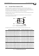
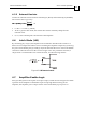

Table Of Contents
Raven Installation Guide Servo Control Operation
MAN-RAVIG (Ver. 1.1)
4-4
4.5.2 External Resistor
Connect an external resistor between terminal J2/3 (ECLP) and terminal J2/2 (ECLRET).
The resistor value is given by:
0 < R
ECLP
< 11.4 K (1/8 Watt)
At R
ECLP
greater than 11.4K, the current limit will be internally clamped to the
nominal value.
I
P(nom)
is the nominal peak current limit of the amplifier.
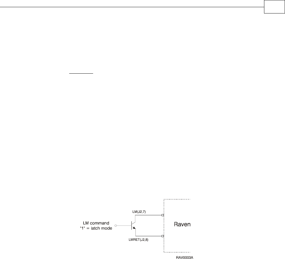
4.6 Latch Mode (LM)
By connecting J2/7 to J2/8, the amplifier can be latched to Disable mode whenever a
Short or Over Temperature failure occurs. Disabling the amplifier temporarily (removing
the power from Enable pins J2/9 and J2/10) resets the latch. Be sure to restore the Enable
connection when the reason for the event no longer exists. For permanent selection, a
simple short is recommended. For remote selection, use the following scheme.
Figure 4-2: LM Remote Control
4.7 Amplifier Enable Logic
Pins J2/9 and J2/10 are the inputs of an opto-coupler, which must be energized to enable
operation of the amplifier. If the Enable input is kept high before turning on the
amplifier, the amplifier power output will be active immediately upon power on.
(Kohm) = 12.5 *
R
ECLP
Ip(new)
Ip(nom)
- 1
(Kohm) = 12.5 *
R
ECLP
(Kohm) = 12.5 *
R
ECLP
Ip(new)
Ip(nom)
- 1