
Network Hardware User Manual

HARSFEN0602
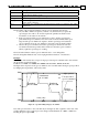
Example:
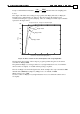
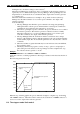
This example demonstrates the smoothing filter and the smoothing factor SF.
Let us MO=1; JV=4000; AC=100000; DC=100000; SD=10
6
; PM=1; RM=0; BG; with three
different values of SF.
1. The SF=0 graph displays sharp corners, since smoothing is ignored, therefore non-continuity
of acceleration is allowed.
2. The SF=10 graph takes 10 milliseconds more to stabilize the speed software command,
however the speed reference profile is much smoother.
3. For the SF=50 graph, the smoothing is so strong with respect to the total acceleration time
that the AC acceleration is never reached.
0
0.02
0.04
0.06
0.08
0.1
0
500
1000
1500
2000
2500
3000
3500
4000
SF=0
SF=10
SF=50
Time (sec)
Speed reference
(count/sec)
Figure 18 – Speed command for different smooth Factor
Note: The profiler smoothes the motion and decreases (may also prevent) overshoots, while
introducing a delay in the controller response.
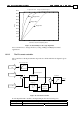
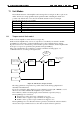
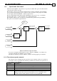
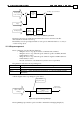
11.2.2 The auxiliary speed command
The auxiliary speed reference is generated according to the block diagram below. The
parameters relevant to the auxiliary speed command generation are:
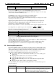
Command Description
AG[2] Analog input gain, counts/sec/Volt.
AS[1] Analog offset
FR[2] Follower gain
RM Reference mode – 1 to use the auxiliary speed command, 0 to null the auxiliary
speed command.