
Laser Pointer User Manual

- 17 -
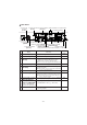
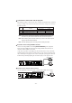
Analogue RGB signal
10 9 8 7 6
54321
15 14 13
DSUB 15P shrink terminal
(
Female
)
Pin No. Name
1 Video signal (Red)
2 Video signal (Green)
3 Video signal (Blue)
4 N.C
5 GND
12 11
Signal allocation
Pin assignment
Video signal
Horizontal synchronized signal
Vertical synchronized signal
Analogue 0.7V(p-p) 75 terminated
TTL level (positive/negative polarity)
TTL level (positive/negative polarity)
Pin No. Name
6 GND (Red)
7 GND (Green)
8 GND (Blue)
9 N.C
10 GND
Pin No. Name
11 GND
12 N.C
13 Horizontal synchronized signal
14 Vertical synchronized signal
15 N.C
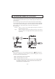
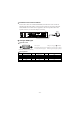
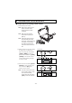
AC IN
MOUSE INPUT
S-VIDEO
VIDEO L AUDIO R
AUDIO
(
L/R
)
1
AUDIO
(
L/R
)
2
RGB OUT
RGB2
RGB1
OUTPUT
ON
OFF
POWER
USBEthernet
RS-232CDC12V
Monitor
Connection to the S video-in terminal
Connect the S video-out terminal (mini DIN 4P) of the Presenter to the S video-in
terminal of the TV/video monitor. For the S video mode, use an S video connection
cable available on the market. If the equipment to be used is provided with a Y/C
separate connector, a conversion adapter is necessary.