VISUAL PRESENTER HV-8000SX INSTRUCTION MANUAL VISUAL PRESENTER Please read this instruction manual carefully before using this Visual Presenter and keep it for future reference.
IMPORTANT SAFEGUARDS recommended by the manufacturer, or sold with the product. Any mounting of the product should follow the manufacturer's instructions, and should use a mounting accessory recommended by the manufacturer. Read Instructions – All the safety and operating instructions should be read before the appliance is operated. Retain Instructions – The safety and operating instructions should be retained for future reference.
Grounding or Polarization – This product may be equipped with either a polarized 2-wire AC line plug (a plug having one blade wider than the other) or a 3-wire grounding type plug, a plug having a third (grounding) pin. The 2-wire polarized plug will fit into the power outlet only one way. This is a safety feature. If you are unable to insert the plug fully into the outlet, try reversing the plug. If the plug still fails to fit, contact your electrician to replace your obsolete outlet.
Damage Requiring Service – Unplug this product from the wall outlet and refer servicing to qualified service personnel under the following conditions: Safety Check – Upon completion of any service or repairs to this product, ask the service technician to perform safety checks to determine that the product is in proper operating condition. When the power-supply cord or plug is damaged.
SA 1965 SA 1966 The lightning flash with arrowhead symbol, within an equilateral triangle, is intended to alert the user to the presence of uninsulated "dangerous voltage" within the product's enclosure that may be of sufficient magnitude to constitute a risk of electric shock to persons. This marking is located at the bottom of product. INFORMATION This equipment has been tested and found to comply with the limits for a Class A digital device, pursuant to Part 15 of the FCC Rules.
BEFORE YOU USE Use the Visual Presenter under the rated electrical conditions. Do not leave the Presenter under direct sunlight or by heaters, or the Presenter may be discolored, deformed, or damaged. Do not place the Presenter in any humid, dusty, windy or vibrating location. Use the Presenter in the following environmental conditions: Temperature: 5°C~35°C (41°F~95°F) Humidity: 30%~85% (No condensation) Use a soft, dry cloth for cleaning. Do not use any volatile solvent, such as thinner or benzine.
CONTENTS 1. PART NAMES AND FUNCTIONS .................................................... 8 Appearance .................................................................................................. 8 Front Panel .................................................................................................. 8 Operation Panel .......................................................................................... 9 Rear Panel ...........................................................................
. OSD (On-Screen Display) ............................................................. 33 Main menu ................................................................................................... When the white balance is set ..................................................................... When the gamma is set ............................................................................... When the microphone volume is set ...........................................................
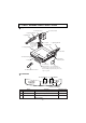
1. PART NAMES AND FUNCTIONS Appearance 3. Camera Head 12. Infrared Sensor 6. Lighting Unit Arm 5. Lighting Unit 4. Column Lock Rerease Button 9. Carryng Handle 2. Column Press this button to raise/fold the column. 6. Lighting Unit Arm 5. Lighting Unit 11. Power Switch 13. Mic Jack (MIC) 10. LCD Monitor Bracket Socket 1. Stage 7. Front Panel 15. Scroll Mouse 8. Operation Panel 14. Wireless Remote Control Usually, this panel is kept inside the main body.
Operation Panel 20. Monitor Output Buttons 25. Freeze Button 24. Image Rotation Button 30. Focus Buttons 26. Image Transfer Button 28. Contrast Button 27. White Balance 21. Magnification Button Button 19. Input Selection Buttons 22. Color/B&W Selection Button 29. Iris Buttons 23. Posi/Nega Conversion Button Name Function Reference Page 19. Input Selection Buttons To change the input line. P.22 20. Monitor Output Buttons To select the signal for outputting to the NTSC/PAL monitor. P.23 21.
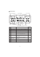
Rear Panel 31. Power Cord Receptacle [AC IN] 33. 12VDC Out Terminal 35. RS-232C Terminal 40. Audio-out Terminal 43. Audio-in Terminal 1 [DC12V] [RS-232C] 41. Video-in Terminal 1 AUDIO (L/R)1 AC IN POWER ON DC12V RS-232C VIDEO L AUDIO R S-VIDEO RGB OUT RGB1 RGB2 AUDIO (L/R)2 OFF Ethernet 32. Power Switch [POWER] USB MOUSE OUTPUT 37. USB Terminal [USB] ABCD INPUT 42. Video-in Terminal 1 34. Mouse Terminal [MOUSE] 38. Analogue RGB-out Terminal [OUTPUT.RGB OUT] 39. Vide-out Terminal 44.
Name Function Reference Page P.22, P23 41. Video-in Terminal 1 Video signal from this terminal is output through the analogue RGB-out terminal when the input selection is set at RGB1. 42. Video-in Terminal 2 Video signal from this terminal is output through the analogue RGB-out terminal when the input selection is set at RGB2. P.22, P23 43. Audio-in Terminal 1 Audio signal from this terminal is output through the audio-out terminal when the input selection is set at RGB1. P.22, P23 44.
Wireless Remote Control IRIS OPEN LAMP IRIS CLOSE MOVE IRIS NORMAL PRESET FOCUS NEAR FOCUS FAR 54. [LAMP] 46. [IRIS OPEN] 55. [MOVE] 47. [IRIS CLOSE] 56. [PRESET] 48. [IRIS NORMAL] 50. [FOCUS FAR] 49. [FOCUS NEAR] TELE ZOOM WIDE 52. [ZOOM WIDE] 51. [ZOOM TELE] INPUT AF 57. [AF] 53. [INPUT] Button Name Function Reference Page 46. IRIS OPEN To open the AUTO iris. P.28 47. IRIS CLOSE To close the AUTO iris. P.28 48. IRIS NORMAL To reset the AUTO iris to the initial value.
2. WIRELESS REMOTE CONTROL 30 30 30 30 30 30 30 30 Point the infrared emitting part of the wireless remote control unit at the infrared sensor of the Visual Presenter, located on the top of the column, and press the button for the desired function. The receivable range may be narrowed when the Presenter is placed under sunlight, near an inverter fluorescent lamp or in any other unfavorable surroundings. Depending on the conditions of fluorescent lamps, etc.
3. MOUSE Connect the mouse to the mouse terminal on the rear panel. The mouse can control the display and operation of the OSD Menu screen, mouse pointer and the Electronic enlargement. When the left button of the mouse is clicked, the OSD menu and the pointer are displayed. Set each function with the mouse. Mouse Right button Left button Center button Mouse wheel The mouse is operated as follows: • Left button........................ To display or clear the pointer and menu alternately by clicking.
4. SETTING UP (1) Unfold the lighting unit arms fully until they come to the deadend. Unfold arm 1 and then arm 2 as illustrated. (2) Press the column lock release button, and raise the column until the column lock release button returns to the original position. Make sure that the column has been completely locked. (3) Turn the main camera head as illustrated until it is stopped. (4) Turn the main camera head until the lens faces to the stage.
Connection to the monitor and the projector The following settings of the Presenter can be switched with the DIP switch. Switch the settings according to the connection environment.
Connection to the S video-in terminal Connect the S video-out terminal (mini DIN 4P) of the Presenter to the S video-in terminal of the TV/video monitor. For the S video mode, use an S video connection cable available on the market. If the equipment to be used is provided with a Y/C separate connector, a conversion adapter is necessary.
5. STORING THE PRESENTER (1) Turn OFF the power switch, and unplug the power cord and the video cable. (2) Turn the main camera head as illustrated until it is stopped. Note: Be sure to set the camera head in the illustrated position before storing. Storing the main camera head in any other position may damage the stage surface or the lens. (3) Press the column lock release button, and fold down the main column. Note: The illustration shows the right storage position of the column.
6. OPERATION PROCEDURES Simple steps for presenting printed material (1) Turn ON the power switch. Note: Before turning ON the power switch, connection to the monitor should have been completed. Note: When the power switch is turned ON, the lighting unit lights up. Note: If the power switch is turned ON immediately after being turned OFF, the Presenter may not operate. For restarting, turn OFF the Presenter and wait several seconds then turn ON. (2) Place the object on the stage.
Simple steps for showing transparent material, such as overhead transparencies or slide film Front panel (1) Press the base button [BASE] on the front panel or the lamp button [LAMP] on the wireless remote control to light up the base light (transparent lighting unit) built in the stage. Wireless remote control IRIS OPEN (2) To present a nega film, press the posi/nega conversion button [POSI / NEGA] on the operation panel to change the mode to [N] (Negative).
7. VARIOUS FUNCTIONS Lighting The upper lighting unit for presenting material such as printed matter and 3-D objects, and the baselight for presenting transparent material, such as slide, and negative films, are built in to the Presenter. When the lamp button [LAMP] ( [UPPER] / [BASE] ) on the front panel or the lamp button [LAMP] on the wireless remote control is pressed, the fluorescent lamp lights up in 1 to 3 seconds.
Front panel Zoom Press the zoom button [TELE] on the front panel or wireless remote control, and the image will gradually be enlarged. Wireless remote control TELE ZOOM WIDE Front panel Press the zoom button [WIDE] on the front panel or wireless remote control, and the image will gradually be reduced.
Table of Video- and Audio-in / out Terminal Selections Output signal Video-out Terminal RGB Input Main Unit Audio-out Terminal L R Main camera video signal Microphone Monaural Main camera video signal RGB1 External video signal 1 RGB1 External audio signal 1 Stereo 1 (L/R) Microphone Monaural Main camera video signal RGB2 External video signal 2 RGB2 External audio signal 2 Stereo 2 (L/R) Microphone Monaural Output to the monitor Select the signal to be output to the NTSC/PAL monitor.
Table of Corresponding Signals Frequency Signal Mode name VGA1 VGA2 VGA3 VGA@60Hz VGA@72Hz VGA@75Hz VGA@85Hz SVGA@56Hz SVGA@60Hz SVGA@72Hz SVGA@75Hz SVGA@85Hz XGA@60Hz XGA@70Hz XGA@75Hz XGA@85Hz SXGA1 SXGA2 SXGA3 SXGA@60Hz SXGA@75Hz SXGA@85Hz UXGA@60Hz UXGA@65Hz UXGA@70Hz UXGA@75Hz UXGA@85Hz Mac 13 Mac 16 Mac 19 Mac 21 PC98 Horizontal kHz 37.861 37.861 37.972 31.469 37.861 37.500 43.269 35.156 37.879 48.077 46.875 53.674 48.363 56.476 60.023 68.677 67.500 60.000 85.938 63.981 79.976 91.146 75.000 81.
Electronic enlargement To double the image. To double the central part of the image, press the button [MAGNIFICATION] on the operation panel. When double magnification is selected, the indicator lamp lights up. The image can be enlarged only within the shooting area of the main camera. The mouse can be operated as follows: Operation panel • Left button ......................... To scroll the image according to the dragging of the mouse while holding down the left button. • Mouse wheel...................
Posi / Nega conversion To show a negative film. Press the posi/nega conversion button [POSI / NEGA] on the operation panel or wireless remote control, the indicator lamp lights up and the image will be converted accordingly. When the posi/nega conversion button [POSI / NEGA] is pressed again, the indicator lamp goes out and the normal mode is resumed. Operation panel Image rotation When the image rotation button [IMAGE ROTATION] on the operation panel is pressed, the image rotates.
Contrast To present the material with a little half tone such as documents. Images with sharp characters and lines contrasty with background can be obtained. When the contrast button [CONTRAST] on the operation panel is pressed, the indicator lamp lights up, and the image becomes contrasty. When the contrast button [CONTRAST] is pressed again, the indicator lamp goes out, and the image is reset to the normal condition.
Iris To adjust the Auto iris level of the lens. Press the iris button [OPEN] on the operation panel or the iris open button [IRIS OPEN] on the wireless remote control, and the iris will open. Press the iris button [CLOSE] on the operation panel or the iris close button [IRIS CLOSE] on the wireless remote control, and the iris will close. Press the iris normal button [IRIS NORMAL] on the wireless remote control, and the initial setting will be resumed.
Focus Auto Focus Front panel Press the auto focus button [AUTO FOCUS] on the front panel or the auto focus button [AF] on the wireless remote control, and the auto-focus will be Wireless remote control activated. INPUT AF While the auto-focus is in operation, the indicator lamp on the front panel blinks until the object is brought into focus. The Presenter features a one-push auto Front panel focus function.
Powered Manual Focus To focus on specific part of the material, such as 3-D material. Press the focus button [NEAR] or [FAR] on the operation panel or the focus button [FOCUS NEAR] or [FOCUS FAR] on the wireless remote control. Note: The auto focus functions up to approx. 10cm (3.9 in.) above the stage surface (with the close-up lens attached).
LCD monitor bracket socket The LCD monitor bracket socket is used for attaching an LCD monitor (optional) with an LCD monitor bracket (optional). LCD Monitor (optional) LCD Monitor bracket (optional) LCD Monitor bracket socket Connecting to the LCD monitor out terminal The LCD monitor (LM-5011N) can be connected by using the LCD monitor out terminal of the Presenter. Note: When connecting to the LCD monitor out terminal, confirm the right connection direction.
PC link software “Image Mate” When the “Image Mate” is installed in the PC, the following operations are available: • Image data transfer to the PC • Operation of the Presenter by the PC For details, refer to the installation manual of “Image Mate” and “manual.pdf” in the CD-ROM.
8. OSD (On-Screen Display) Main menu Icon Name Function Upper light ON/OFF To turn ON/OFF the upper light. When the Presenter is turned ON, the upper light remains at the previously saved settings. Base light ON/OFF To turn ON/OFF the base light. When the Presenter is turned ON, the base light remains at the previously saved settings. Color/B&W selection To switch the selection of the color/B&W of the screen.
Icon When the white balance is set Name Function Pointer To change the color and shape of the pointer on the screen. Every time the left button of the mouse is clicked, the icon pointer is switched in order of “White arrow Blue arrow Yellow arrow Red arrow” and “White line Blue line Yellow line Red line”. Status saving To save each status of the current aperture, lighting, white balance, preset zoom angle of view, gamma, auto iris level and microphone level.
Icon Name Function White balance To display the White Balance Adjustment menu. When the left button of the mouse is clicked again, the White Balance Adjustment menu is closed. Auto To set the white balance in the AUTO FOLLOW mode (initial setting). One-push To set the push-set white balance. When the left button of the mouse is clicked, the white balance for the then color temperature is fixed. Manual To set the white balance with , and .
9. NETWORK FUNCTIONS By connecting this Presenter to the network using Ethernet (10BASE-T/100BASE-TX), the following functions are made available from the host (e.g., PC) on the network: • Web server functions – Displaying quasi-moving images, displaying static images and operating remote control through the Web browser. • FTP client functions – Saving image files in the remote host by using the image transfer button [IMAGE TRANSFER]. • FTP server functions – Transferring image files.
Connection to the network • Connection using HUB Connect the Ethernet terminal (RJ-45) of the Presenter to the HUB port with an Ethernet straight cable (UTP Category 5). For the HUB port, use a port other than the cascade port.
• Then, the Configurations page is displayed. Confirm the settings, and click the link [Network Configuration].To display the Network Setting Input page, the authentication by the login password is required. When the entry of the password is requested, enter [root] for the user name and enter the password set at the Network Setting Input page. No password has been factory set. When the Presenter remains in the factory set condition, enter no password.
Initialization of the network settings If the connection from the network is disabled due to destruction of the network settings or disremembering of the set value, reset the settings to the factory settings by using the following procedure and then redo the settings: • If the Presenter is in connection to the network, disconnect the Presenter from the network. • In the power supply OFF state, lower the [D] key of the DIP switch key on the backside of the Presenter to [1].
Display of quasi-moving images When the link [LIVE] is clicked at the HV-800SX/8000SX/8500SX page, another window opens, and a quasimoving live image is displayed. However, to display quasi-moving images, Java and JavaScript must have been set enabled. If the Presenter is used in the environment where Java or JavaScript are not set enabled, click the link [REFRESH]. Then, a page that renews static images at specified intervals is be displayed.
Operation of remote control When the link [CONTROL] at the quasi-moving image page is clicked, the CONTROL page is displayed. At the CONTROL page, the lighting can be changed, the zoom can be adjusted, the iris can be adjusted, the focus can be adjusted, the color/B&W can be switched, the posi/nega can be switched, the aperture can be adjusted, the contrast can be adjusted and the color tone (RGB) can be adjusted, all through remote control. Click the button for intended operation.
Setting up • Start the Web browser from the host connected to the Presenter. • Enter the IP address or host name (if allocated) of the Presenter, following [http://], in the address column of the Web browser provided for entering the URL to be opened. • When the HV-800SX/8000SX/ 8500SX page is displayed in the Web browser, click the link [SET UP]. • Then, the Configurations page is displayed. Confirm the settings, and click the link [FTP Client Configuration].
Operation Operation panel • Check to confirm the image to be saved on the monitor. • Press the image transfer button [IMAGE TRANSFER] on the operation panel. • LED on the button blinks. When the LED goes out, saving is completed. Now, the next image can be saved. • When the image cannot be saved, the LED on the button in blinking lights up. Then, check the settings and the like. To turn OFF the LED in lighting, press the image transfer button [IMAGE TRANSFER] again.
Appendix Setting items of the network Item Outline IP Address The IP address of the Presenter. Specifies the value allocated by the administrator of the network in use. Factory set to 192.168.0.100. Subnet mask The mask value for separating the network address from the host address. Used in combination with the IP address to specify the network to which this Presenter belongs.Specifies the value allocated by the administrator of the network in use. Factory set to 255.255.255.0.
Specifications of the FTP server Port: No. 21 Connection time-out: 15min Number of connections at the same time: 1 Corresponding command Command Operation Response USER To enter the user name 331, 500, 530 PASS To enter the password 230, 500, 503, 530 PORT To notify the data port No.
10. RS-232C SPECIFICATIONS The Presenter can be controlled by a PC connected to the Presenter through the RS232C terminal [RS-232C]. Setting up (1) Connect the Presenter to a PC with an RS-232C connection cable. Note: When using an RS-232C cable available in the market, make sure of the connection shown the next page. Note: To protect the Presenter and the PC, be sure to turn OFF all the power switches of all equipment before connecting.
Table of the communication commands Function Command Parameter Data Comments Command to execute the one-step Auto Focus. Auto Focus AF Focus adjustment FO (NEAR) (FAR) (STOP) Command to adjust the Focus. Zoom adjustment ZO (TELE) (WIDE) (STOP) Command to adjust the Zoom. Iris adjustment IR (OPEN) (CLOSE) (STOP) (AUTO) Command to adjust the Iris. Lighting selection PL (OFF) (BASE) (UPPER) Command to select the Lighting.
Function Command Gamma switch GM Parameter (1.0) (0.9) (0.8) (0.7) (0.6) (0.5) (0.4) (0.3) Data Command to switch the gamma set value of the image. Image rotation RO (OFF) (90°) (180°) (270°) Command to rotate the image. Aperture selection AP (OFF) (ON) Command to switch the modulation (edge emphasis) of the image. White balance selection AW (OFF) (AUTO) (ONE-PUSH) Command to switch the mode of the white balance. Contrast selection CT (OFF) (ON) Command to switch the contrast settings.
Transmission Command (PC Visual Presenter) Each operation command is executed in ASCII code, and transmitted in a set of 7 bytes as follows: S T X (PC) Command (Visual Presenter) Parameter E T X Data ACK Response data format (Visual Presenter PC) All response data is transmitted as ASCII code, and it coverds parameter of the table of operation command.
Transmission specifications • • • • • • • Full duplex start-stop sync. mode Start bit Data bit Stop bit Parity bit X parameter Baud rate (Communication speed) : 1 bit : 8 bits : 1 bit : None : None : 9600bps Connection If the RS-232C cable is not correctly connected between the Presenter and the PC, no acknowledgement is transmitted.Connect the RS-232C cable correctly, and fix it firmly with the connector set screws before the operation.
11. TROUBLESHOOTING HINTS Symptom Possible cause / countermeasure No Images on TV monitor • Cable is not properly connected to the video-in terminal of monitor. • The power cord is disconnected from the wall AC outlet. • The plug is disconnected from the power cord receptacle of the Presenter. • The power switch is not turned ON. • Zoom is set at TELE to display only white/black part of the material. • The power switch is turned ON immediately after it is turned OFF.
12. SPECIFICATIONS General Specifications Item Power source Power consumption Outside dimensions AC100-240V 50Hz/60Hz 0.7A-0.3A 533mm(W) X 449mm(D) X 185mm(H) (21.0 X 17.7 X 7.3 in) (When folded) 766mm(W) X 449mm(D) X 628mm(H) (30.2 X 7.7 X 24.7 in) (When set up) Weight Input selection Output terminal 10.5kg (23.
Main camera Specifications Item Lens Shooting speed Shooting area f = 7.2 - 72mm (10 - time zoom), F2.8 7.5 frames / sec 362mm(H) X 290mm(V) (14.3 X 10.2 in) max. 40mm(H) X 32mm(V) (1.6 X 1.3 in) min. Limit of focus adjustment From the stage surface to 100mm (3.9 in) above the stage surface Zooming Focusing Iris Image pick-up element Total picture elements Effective picture element Sync.
Lighting Item Specifications Upper High frequency lighting mode, 3-wave-length type fluorescent lamp 6W (Model: FHL6EX-N) Base High frequency lighting mode, 3-wave-length type fluorescent lamp Area size: 296mm (W) X 216mm (H) (11.7 X 8.5 in.) Supplied accessories Name Quantity Power cord (2.5m) Video-audio cable (2m) Scroll mouse Infrared wireless remote controller (RCW-632) Batteries (Type R03, AAA) LCD monitor connection cable VGA cable (D .
WARNING: Unauthorized recording of copyrighted slide films, materials, photographs, etc. may infringe on the rights of copyright owners and be contrary to copyright laws. ELMO CO., LTD. 6-14, Meizen-cho, Mizuho-ku, Nagoya, 467-8567, Japan OVERSEAS SUBSIDIARY COMPANIES U.S.A. Canada ELMO Mfg. Corp. 1478 Old Country Road, Plainview, NY 11803-5034 Tel:(516)501-1400 Fax:(516)501-0429 E-mail:elmo@elmousa.com web:http://www.elmousa.com ELMO Canada Mfg. Corp.