PAN • TILT • ZOOM COLOR CAMERA PTC-200C INSTRUCTION MANUAL Please read this instruction manual carefully before using this PTC-200C and keep it for future reference.
IMPORTANT SAFETY INSTRUCTIONS 1. Read these instructions. 2. Keep these instructions. 3. Heed all warnings. 4. Follow all instructions. 5. Do not use this apparatus outdoors. 6. Do not use this apparatus near water. 7. Clean only with dry cloth. 8. Do not install near heat sources such as radiators, heat registers, stoves or other apparatus (including amplifiers) that produce heat. 9. Do not touch this apparatus during lightning storms. 10.Unplug when unused for long periods of time. 11.
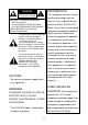
INFORMATION CAUTION RISK OF ELECTRIC SHOCK DO NOT OPEN CAUTION : TO REDUCE THE RISK OF ELECTRIC SHOCK. DO NOT REMOVE COVER (OR BACK). NO USER SERVICEABLE PARTS INSIDE. REFER SERVICING TO QUALIFIED SERVICE PERSONNEL. The lightning flash with arrowhead symbol, within an equilateral triangle, is intended to alert the user to the presence of uninsulated "dangerous voltage" within the product's enclosure that may be of sufficient magnitude to constitute a risk of electric shock to persons.
HANDLING PRECAUTIONS Be sure to use the provided AC adapter. Do not leave the Camera under direct sunlight or by heater, or the Camera may be discolored, or damaged. Do not place the Camera in any humid, dusty, windy or vibrating location. Use the Camera in the following environmental condition: Temperature: 0 °C ~ 40 °C (32 ° ~ 104 °F) Humidity: 30% ~ 85% (No condensation) Use a soft, dry cloth for cleaning. Do not use any volatile solvent, such as thinner or benzine.
CONTENTS IMPORTANT SAFETY INSTRUCTIONS .........................................1 HANDLING PRECAUTIONS ............................................................3 1. PART NAMES AND FUNCTIONS....................................................5 2. WIRELESS REMOTE CONTROLLER .............................................7 3. SETTING UP ....................................................................................9 4. OPERATION PROCEDURES ........................................................
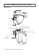
1. PART NAMES AND FUNCTIONS Overall View LED INFRARED SENSOR BASE LENS CAMERA HEAD ALARM IN TERMINAL RS-485 IN TERMINAL TERMINAL BLOCK DIP Switch (4) DIP Switch (10) RS-485 OUT TERMINAL ALARM OUT TERMINAL DC IN INFRARED SENSOR COMPOSITE-VIDEO OUT (RCA pin jack) This camera is designed to mount on ceiling panels only.
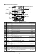
Wireless Remote Controller 15 RESET 1 POWER 14 BACK LIGHT 16 PRESET 2 OPEN 17 ID 5 NEAR 18 NUMBER (1 6) 3 CLOSE 6 FAR 4 AUTO 7 AUTO 11 HOME 10 Directions 8 TELE 9 WIDE 12 MENU No. 1 2 3 4 5 6 7 8 9 10 11 12 13 14 15 16 17 18 13 CURSOR/PAN-TILT Button Name POWER OPEN CLOSE AUTO NEAR FAR AUTO TELE WIDE Direction Function To turn ON/OFF the Camera power. To open the iris manually. To close the iris manually. To iris automatically. To move the focus near. To move the focus far.
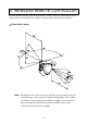
2. WIRELESS REMOTE CONTROLLER Point the infrared emitting window of the wireless remote controller at the infrared sensor of the Camera, located at the front, and the rear panel, and select the desired function. Receivable range Note: The infrared sensors may receive the infrared rays only within a narrower receivable range or may not receive them at all depending on the ambient environment, such as being placed under the sunlight or near an inverter fluorescent lamp.
Preparation Remove the battery case cover by pressing downward on the [ ] mark part in the direction as indicated by the arrow. Install 2 pcs. of batteries (type R03,AAA) into the case in the direction as indicated there. Note: Install the batteries with the proper to and to polarity. Note: For dry cells, be sure to use the size AAA. Note: Change the batteries at least once a year or when even nesessary.
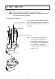
3. SETTING UP [1] Installation Note: When carrying the Camera, be sure to hold the base. Note: Do not turn the Camera head in the PAN-TILT direction by hand, or the Camera head may be broken. (1) Mounting the Fixing Plate • Put 4 Hexagon Head Bolts M5x40 (supplied) SCREW M3x5 (attached) , 4 PCS through the Fixing Plate, and screw the Fixing Plate to the Main Unit with 4 Screws M3x5 (supplied).
(2) Making mounting holes to the Ceiling Tile • Make 4 holes of 8mm (5/16 in.) to the Ceiling Tile as shown. MOUNTING HOLE 8mm (5/16 in.), 4 LOCATIONS 102mm (4 in.) 70mm (2-3/4 in.) BACK 54mm (2-1/8 in.) FRONT CEILING TILE (t 1/2 in. 1 in.
(3) Fixing the Main Unit • Put the Ceiling Tile between the Main Unit and the Ceiling Plate, and fix the Main Unit by fastening 4 Wing Nuts. WING NUT M5 (supplied), 4 PCS CEILING PLATE MOUNTING HOLE: 5/16 in.
(4) Mounting the Safety Wires • Loop up one end of the Safety Wires through the respective safety wire looping holes made on the Ceiling Plate, and then loop up the other end of the same around the beams or anything that is used to mount ceiling tile channel for structure safety.
Connection examples for the Camera - 13 -
4. OPERATION PROCEDURES [1] Power supply to the Camera The Camera has no POWER switch. Power is supplied to the Camera when the AC adapter is connected to the wall socket and the Camera. When power is supplied to the Camera, the Camera turns to the right and then to the center automatically (viewed from the front), returning the Camera position to the detault home position.
[3] Operating PAN/TILT • While watching the screen, press any of 15 11 10 10 (UP, DOWN, LEFT, RIGHT) direction buttons for the direction in which you want to watch the image. • To change the direction minutely, jog the direction button. To change the direction largely, hold down the direction button. • Two operation modes are available according to the speed: AUTO mode changing the speed according to the zoom position, and MANUAL mode setting the speed manually.
[4] Lens operation (1) Zoom operation • The object is zoomed in (appears larger in the screen) when 8 TELE button of ZOOM is pressed, or zoomed out (appears smaller in the 2 5 3 6 screen) when pressed. 4 7 9 WIDE button of ZOOM is • When 8 TELE button or 9 WIDE button is held down for over one second, the zoom speed increases. 8 9 (2) Focus operation • When 7 AUTO button of FOCUS is pressed, FULL AUTO FOCUS status is established.
[5] BLC (Back Light Control) In case the back lighting is too bright to shoot the 14 main object clearly, press 14 BACK LIGHT button. To cancel this mode, press the button. [6] Preset operation 16 18 The Camera head direction, the zoom position, the focus status and the brightness level can be registered for as many as six settings. The registration contents will be retained even if the Camera power is turned OFF.
5. THE ID NUMBER SETTING When multiple Cameras are laid out adjacently and operated via the wireless remote controller, the Cameras receiving the infrared rays operate in unison in the same way. When each Camera is allocated with a different ID No., the Camera can be controlled independently when its ID No. is specified via the wireless remote controller. The ID Nos. can be allocated for up to 6 Cameras. (1) Setting an ID No. • Turn ON only the camera to be set with an ID 17 18 12 No.
6. OSD (On-Screen Display) 1 14 The 12 MENU button is used to turn ON/OFF the OSD display. When the Sub menu is displayed, the screen goes back to the previous screen. When the OSD display is available, 11 12 10 10 direction buttons and 11 HOME button function as the menu operation keys. To halt the menu operation and perform the PAN- 13 TILT operation, press 13 CURSOR/PAN-TILT button. To resume the menu operation, press CURSOR/PAN-TILT button again.
<6> ALARM IN Sets the alarm position time [10 sec (default), 20 sec, 30 sec, 1 min, 5 min, 10 min, OFF]. When the set time has passed, automatic resetting is made to the lastly executed preset position. <7> ALARM OUT Sets the alarm signal output time [0.1 sec (default), 0.5 sec, 1 sec, 2 sec, 5 sec, 10 sec, 30 sec]. (2) CAMERA SETUP SELECT <1> BLC ADJUST (Return to 12 MENU ) ON/OFF: To balance the difference between light and dark background.
*1: <9> "R SHIFT" and <10> "B SHIFT" are available in 2 types, respectively: one for the ATW and AWC functions, and the other for the INDOOR, OUTDOOR and LIGHT functions. For example, it is possible to set "R SHIFT" to +10 in the ATW mode and to ± 0 in the INDOOR mode. *2: <11> "COLOR" is available for all modes irrespective of the mode of "WB". *3: To change and save the Camera settings, be sure to press 11 HOME button in the >MEMORY display on P. 1.
7. ALARM IN/OUT TERMINALS [1] Alarm input By short-circuiting the ALARM 1 IN or ALARM 2 IN Terminal Block to the GND terminal on the Terminal Block, the Camera moves to the allocated preset position. • When short-circuiting the ALARM 1 IN terminal to the GND terminal, the Camera moves to the preset position 1. • When short-circuiting the ALARM 2 IN terminal to the GND terminal, the Camera moves to the preset position 2.
8. ALL CLEAR SWITCH The PAN-TILT settings, the LENS settings, the preset settings, the ID settings and the Camera settings by means of the OSD can be reset to the factory-settings by turning ON the switch No. 2 of the DIP Switch (4) on the bottom of the Camera before turning ON the power supply to the Camera and then turning OFF the same switch after turning ON the power supply to the Camera. Note: For all other switches (No. 1, No. 3 and No.
9. RS-485 This system can be controlled from the PC by connecting the RS-485 terminal on the 9-pin Terminal Block to the PC via an RS-485 converter. Make the connection as shown below. Each camera can be set for the ID address via a 10-pin DIP Switch located on the bottom so that a selected camera can be controlled. Up to 223 Cameras can be controlled from one PC. To raise the reliability, connect the DATA (+)and the DATA (-) with a twist pair cable.
10. TERMINATING RESISTANCE AND ID ADDRESS SETTINGS The ID address of the RS-485 and the terminating resistance can be set by using the switches Nos. 1 through 9 of the DIP Switch (10) located on the bottom of the Main Unit. Switch No. 1–8 9 10 Function Sets the ID address. Turns ON/OFF the terminating resistance None [1] Setting the terminating resistance The terminating resistance is built in each Camera, and it can be turned ON/OFF by using the pin No. 9 of the DIP Switch (10) of each Camera.
Setting the ID address Camera ID address Disabled 1 2 3 4 5 6 7 8 9 10 11 12 13 14 15 16 17 18 19 20 21 22 23 24 25 26 27 28 29 30 31 32 33 34 35 36 37 38 39 40 41 42 43 44 45 46 47 48 49 50 51 52 53 54 55 1 OFF ON OFF ON OFF ON OFF ON OFF ON OFF ON OFF ON OFF ON OFF ON OFF ON OFF ON OFF ON OFF ON OFF ON OFF ON OFF ON OFF ON OFF ON OFF ON OFF ON OFF ON OFF ON OFF ON OFF ON OFF ON OFF ON OFF ON OFF ON Switch No.
Camera ID address 112 113 114 115 116 117 118 119 120 121 122 123 124 125 126 127 128 129 130 131 132 133 134 135 136 137 138 139 140 141 142 143 144 145 146 147 148 149 150 151 152 153 154 155 156 157 158 159 160 161 162 163 164 165 166 167 1 OFF ON OFF ON OFF ON OFF ON OFF ON OFF ON OFF ON OFF ON OFF ON OFF ON OFF ON OFF ON OFF ON OFF ON OFF ON OFF ON OFF ON OFF ON OFF ON OFF ON OFF ON OFF ON OFF ON OFF ON OFF ON OFF ON OFF ON OFF ON Switch No.
11. TROUBLESHOOTING HINTS Symptom Possible cause/remedy No images on TV monitor • Cable is not properly connected to the video-in terminal of monitor. • The AC adapter is disconnected from the wall AC outlet. • The AC adapter output plug is disconnected from the DC jack of the Camera. • Zoom is set at TELE to display only white/black part of the material. • The LED is lit red, and the Camera is in the OFF position. • The LED is lighting, and the OFF Timer mode of the Camera power is working. (See P.
12. SPECIFICATIONS General Item Power source Current consumption Outside dimensions Weight /Mass Television system Output terminal Control terminal Power terminal Specifications 12V DC MAX.1A 124mm(W) X 153mm(D) X 136mm(H) (4.9 X 6.0 X 5.4 in.) mainbody only: 800g (1.8 lb), with plates: 1,100g (2.
Pan/Tilt Item Pan range Tilt range Pan Tilt Speed Specifications Left 150° Right 150° Up 30° Down 90° Auto/manual (8 speed) Other Item Title setting Daisy chain connection Specifications Provided (Camera/preset selection) Max 223 (PTC-200C) cameras 13. SUPPLIED ACCESSORIES Item AC adapter Model NO: D12-10-1000 (5Z0494) (rated input AC120V 60Hz) Wireless remote controller (RCW-PTZS) Batteries (Type R03,AAA) BNC/RCA adaptor plug.
WARNING: Unauthorized recording of copyrighted, materials, photographs, etc. may infringe on the rights of copyright owners and be contrary to copyright laws. ELMO CO., LTD. 6-14, Meizen-cho, Mizuho-ku, Nagoya, 467-8567, Japan OVERSEAS SUBSIDIARY COMPANIES U.S.A Elmo Mfg. Corp. 1478 Old Country Road, Plainview, NY 11803-5034 Tel:(516)501-1400 Fax:(516)501-0429 E-mail:elmo@elmousa.com Web : http://www.elmousa.com Canada Elmo Canada Mfg. Corp.
Receivable range - 32 -