
User manual

Duo User Guide
MAN-DUOUG (Ver. 1.0)
3-3
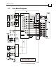
3.4 Connecting the Cables
3.4.1 Wiring the Duo
Once the Duo is mounted, you are ready to wire the device. Proper wiring, grounding and
shielding are essential for ensuring safe, immune and optimal servo performance of the Duo.
Follow these instructions to ensure safe and proper wiring
Use twisted pair shielded cables for control, Feedback and communication connections.
For best results, the cable should have an aluminum foil shield covered by copper braid,
and should contain a drain wire.
The drain wire is a non-insulated wire that is in contact with parts of the cable,
usually the shield. It is used to terminate the shield and as a grounding connection.
The impedance of the wire must be as low as possible. The size of the wire must be thicker
than actually required by the carrying current. A 26 or 28 AWG wire for control and
Feedback cables is satisfactory although 26 AWG is recommended.
Use shielded wires for motor connections as well. If the wires are long, ensure that the
capacitance between the wires is not too high: C < 30 nF is satisfactory for most applications.
Keep all wires and cables as short as possible.
Keep the motor wires as far away as possible from the Feedback, control and
communication cables.
Ensure that in normal operating conditions, the shielded wires and drain carry no current.
The only time these conductors carry current is under abnormal conditions, when
electrical equipment has become a potential shock or fire hazard while conducting
external EMI interferences directly to ground, in order to prevent them from affecting the
drive. Failing to meet this requirement can result in drive/controller/host failure.
After completing the wiring, carefully inspect all wires to ensure tightness, good solder
joints and general safety.
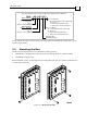
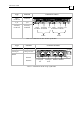
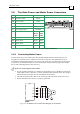
The following connectors are used for wiring the Duo:
Type Function Connector Location
Main Power VL, VP+, PR, PR, PE
Motor Power PE, M1, M2, M3
Table 3-1: Connectors on the “Bottom” of the Duo
Motor Main
Power
Power