
User manual

Duo User Guide
MAN-DUOUG (Ver. 1.0)
3-8
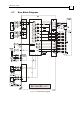
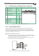
3.8 The Main Power and Motor Power Connectors
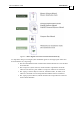
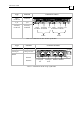
Pin Function Cable Pin Positions
PE Protective earth Power
PR Power return Power
PR Aux. Supply Input Return Auxiliary
VP+ Pos. Power input Power
VL Aux. Supply Input Auxiliary
AC
Motor
Cable
DC
Motor
Cable
M3 Motor phase Motor
Motor
M2 Motor phase Motor
Motor
M1 Motor phase Motor
N/C
PE Protective earth Motor
Motor
Table 3-6: Connectors for Main Power and Motors
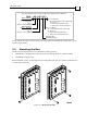
3.8.1 Connecting Motor Power
Connect the motor power cable to the M1, M2, M3 and PE terminals of the relevant axis.
The phase connection order is arbitrary because the Composer will establish the proper
commutation automatically during setup. If several motor/drive combinations are designed
to operate in an identical manner, it is recommended to download the program into all the
drives and connecting them in the same way.
Notes for connecting the motor cables:
For the greatest immunity, it is highly recommended to use a shielded (not twisted)
cable for the motor connection. A 4-wire shielded cable should be used. The gauge is
determined by the actual current consumption of the motor.
Connect the shield of the cable to the closest ground connection at the motor end.
Be sure that the motor chassis is properly grounded.
Figure 3-3: AC Motor Power Connection Diagram for each AXIS.