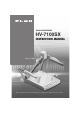
VISUAL PRESENTER HV-7100SX INSTRUCTION MANUAL Please read this instruction manual carefully before using this product and keep it for future reference.
IMPORTANT SAFEGUARDS ■ Read Instructions – All the safety and operating instructions should be read before the appliance is operated. ■ Retain Instructions – The safety and operating instructions should be retained for future reference. ■ Heed Warnings – All warnings on the product and in the operating instructions should be adhered to. ■ Follow Instructions – All operating and use instructions should be followed. ■ Cleaning – Unplug this product from the wall outlet before cleaning.
■ Grounding or Polarization – This product may be equipped with either a polarized 2-wire AC line plug (a plug having one blade wider than the other) or a 3-wire grounding type plug, a plug having a third (grounding) pin. The 2-wire polarized plug will fit into the power outlet only one way. This is a safety feature. If you are unable to insert the plug fully into the outlet, try reversing the plug. If the plug still fails to fit, contact your electrician to replace your obsolete outlet.
■ Damage Requiring Service – Unplug this product from the wall outlet and refer servicing to qualified service personnel under the following conditions: ● When the power-supply cord or plug is damaged. ● If liquid has been spilled, or objects have fallen into the product. ● If the product has been exposed to rain or water. ● If the product does not operate normally by following the operating instructions.
SA 1965 SA 1966 The lightning flash with arrowhead symbol, within an equilateral triangle, is intended to alert the user to the presence of uninsulated "dangerous voltage" within the product's enclosure that may be of sufficient magnitude to constitute a risk of electric shock to persons. This marking is located at the bottom of product.
BEFORE YOU USE ■ Use this product under the rated electrical conditions. ■ Do not leave this product under direct sunlight or by heaters, or this product may be discolored, deformed, or damaged. ■ Do not place this product in any humid, dusty, windy or vibrating location. Use this product in the following environmental conditions: Temperature: 5°C~40°C (41°F~104°F) Humidity: 30%~85% (No condensation) ■ Use a soft, dry cloth for cleaning. Do not use any volatile solvent, such as thinner or benzine.
CONTENTS 1. PART NAMES AND FUNCTIONS Appearance .......................................................8 Front Operation Panel ...........................................9 Rear Panel .......................................................10 Wireless Remote Control .....................................11 1. PART NAMES AND FUNCTIONS 1 2. WIRELESS REMOTE CONTROL 2 3. MOUSE 3 4. SETTING UP AND CONNECTION 4 5. STORING 5 6. OPERATION PROCEDURES 6 7. VARIOUS FUNCTION AND OPERATIONS 7 8. OSD 8 9.
1 1. PART NAMES AND FUNCTIONS 2 2. WIRELESS REMOTE CONTROL 3 3. MOUSE CONTENTS Preset Operation ...............................................33 Image Memory ..................................................34 Splitting the Screen ............................................35 F.A.M. (Frame Accumulate Mode)..........................35 Installation of LCD Monitor ...................................36 Connecting to the LCD Monitor .............................36 "Utility Software CD-ROM" .............
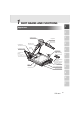
1 PART NAMES AND FUNCTIONS 1 Appearance 2 3 Camera Head Lamp Arm Upper Lamp Lighting Unit Lighting Unit Arm 4 Infrared Sensor Column 5 Scroll Mouse Infrared Emitting Part Column Lock Button Press this button to raise/fold the column.
Front Operation Panel 1 2 Iris 1 Pause 3 White Balance 2 MONITOR OUTPUT RGB1 PAUSE RGB2 F.A.M. OPEN IRIS CLOSE AUTO/MANUAL WHITE BALANCE TELE CONTRAST WIDE MAIN 3 IMAGE ROTATION POSI / NEGA LAMP AF ZOOM UPPER / BASE / OFF 4 4 Monitor Output 5 F.A.M. 6 Image 7 Posi/Nega Rotation Selection Conversion 8 Lamp 9 Contrast 10 Zoom 11 Auto Focus 5 Name 6 7 8 9 10 11 9 Function Reference Page 1 Pause To change the setting between still image and video. P.
Rear Panel 1 6 Analog RGB-in 4 Stereo 5 Analog RGB-out 1 Power Cord 2 12VDC Out 3 RS-232C Audio Terminal Terminal Terminal 1 Terminal Receptacle . Output [RS-232C] [DC12V] [AC IN] [OUTPUT RGB OUT] [INPUT.RGB1] Terminal 2 3 7 Mouse 8 USB 9 Vide-out Terminal 10 Analog RGB-in 11 Terminal Terminal [OUTPUT.S-VIDEO Terminal 2 [MOUSE] [USB] /VIDEO] [INPUT.RGB2] S-Video (mini DIN 4P), Composite video (RCA pinjack) Name Function 1 Power Cord Receptacle [AC IN] Connected to the power cord connector.
Name 1 2 Function Reference Page 10 Analog RGB-in Terminal 2 [INPUT.RGB2] Input image is output through analog RGB-out terminal and video-out terminal when the input selection is set at RGB2. P.22 11 Stereo Audio Input Terminal 1/2 To output input sound from audio output terminal when the input selection is set at RGB1/2. P.22 12 DIP Switch The functions can be switched as follows: P.15 3 ◊[A] key: To switch the resolution of the image output from the RGB output terminal [RGB-OUT].
Button Name Function To change the setting between still image and video. 1 PAUSE Reference Page 2 ELECTRONIC 2X To double the image size. 3 ENLARGEMENT ARROWS To scroll the screen during magnification (electronic enlargement) mode. This button is also used to move the pointer when it appears. P.24 4 MEMORY NO. The memory No. used with 5 to 8 .
1 2 WIRELESS REMOTE CONTROL Receivable Range Point the infrared emitting part of the wireless remote control at the infrared sensor of this product, and press the button for desired function. The receivable range may be narrowed when the Presenter is placed under sunlight, near an inverter fluorescent lamp or in any other unfavorable surroundings. Depending on the conditions of fluorescent lamps, etc. the sensor may fail to receive the infrared light.
3 MOUSE 1 Connect the mouse to the mouse terminal [MOUSE] on the rear panel. Mouse Operation 2 • Click the right button Mouse To display or clear the pointer and OSD menu, operate Right button the OSD menu, drawing function control, screen scroll Left button start and electronic enlargement. Moves in the following sequence during normal use; Displaying pointer → Displaying ENTER icon → Displaying OSD menu → Clearing OSD menu → Clearing ENTER icon → Clearing pointer.
1 4 SETTING UP AND CONNECTION Setting Up (1) 2 Unfold the lamp arms fully until they come to the dead end. Unfold in the sequence specified in the drawing shown to the right. 2 1 3 (2) Press the column lock button, and raise the column until the column lock button returns to the original position. Make sure that the column has been completely locked. (3) Turn the camera head until the lens faces to the stage.
■ Connection to the analog RGB-out terminal Connect the analog RGB-out terminal [OUTPUT·RGBOUT] to the equipment having an analog RGB-in terminal with the analog RGB cable (attached) or a connection cable available on the market. At this time, the position of the display may be deviated from the center. If deviated, manually adjust the horizontal and vertical positions on the connected equipment side. Also, vertical stripes may appear on the screen of the LCD projector.
1 5 STORING Storing When the LCD monitor is mounted, this product cannot be stored. Remove the LCD monitor, and then store this product. 2 (1) Turn off the power switch, and unplug the power cord and the video cable. (2) Turn the camera head so that it may be ready to be stored. 3 4 1 The illustration shows the right storage position of the camera head. Never apply excessive force to the column. 5 (3) Press the column lock release button, and fold down the main column.
6 OPERATION PROCEDURES 1 Simple steps for Presenting Printed Material Front operation panel Wireless remote control 2 LIVE PAUSE MEMORY MONITOR OUTPUT RGB1 PAUSE RGB2 F.A.M.
Steps for Showing Transparent Material 1 Front operation panel Wireless remote control 2 LIVE PAUSE MEMORY MONITOR OUTPUT RGB1 PAUSE RGB2 F.A.M.
7 VARIOUS FUNCTIONS AND OPERATION 1 Lighting Wireless remote control Front operation panel 2 LIVE PAUSE MEMORY MONITOR OUTPUT RGB1 PAUSE RGB2 F.A.M.
Zoom 1 Front operation panel Wireless remote control 2 LIVE PAUSE MEMORY MONITOR OUTPUT RGB1 PAUSE RGB2 F.A.M. OPEN IRIS CLOSE AUTO/MANUAL WHITE BALANCE TELE CONTRAST WIDE 2x SET MAIN IMAGE ROTATION POSI / NEGA LAMP ZOOM PRESET CALL IMAGE CALL POSI/NEGA COLOR/B&W UPPER LAMP BASE MONITOR OUTPUT RGB1 RGB2 MAIN UPPER / BASE / OFF 3 SET AF TELE ZOOM WIDE NORMAL OPEN NEAR FOCUS FAR CLOSE AF IRIS 4 Press the [TELE] button on the front operation panel or the [ZOOM.
Monitor Output Selection 1 Wireless remote control Front operation panel 2 LIVE PAUSE MEMORY MONITOR OUTPUT RGB1 PAUSE RGB2 F.A.M.
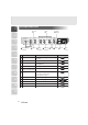
■ External input image signal which can be output from video-out terminal 1 Signal Mode name VGA1 VGA2 VGA3 VGA@60Hz VGA@72Hz VGA@75Hz VGA@85Hz SVGA@56Hz SVGA@60Hz SVGA@72Hz SVGA@75Hz SVGA@85Hz XGA@60Hz XGA@70Hz XGA@75Hz XGA@85Hz SXGA1 SXGA2 SXGA3 SXGA@60Hz SXGA@75Hz SXGA@85Hz UXGA@60Hz UXGA@65Hz UXGA@70Hz UXGA@75Hz UXGA@85Hz Mac 13 Mac 16 Mac 19 Mac 21 PC98 2 3 4 5 6 7 8 Frequency Horizontal Vertical Pixel clock kHz 37.861 37.861 37.927 31.469 37.861 37.500 43.269 35.156 37.879 48.077 46.875 53.
Electronic Enlargement When the [2×] button on the wireless remote control is pressed, the image is enlarged double on the central part. When the pointer is on display and the right button of the mouse is clicked, the target area to be magnified double is highlighted. (Zoom window) When the target area to be enlarged is moved by dragging the mouse and then the left button of the mouse is clicked, the highlighted target area is enlarged.
Color / B&W Selection 1 Wireless remote control To present the B&W (Black&White) material such as documents. A clearer image can be achieved without color blur on a monitor. If the [COLOR/B&W] button on the wireless remote control is pressed, images are switched.
Image Rotation 1 Front operation panel MONITOR OUTPUT RGB1 PAUSE RGB2 F.A.M. OPEN IRIS CLOSE AUTO/MANUAL WHITE BALANCE TELE CONTRAST WIDE MAIN IMAGE ROTATION POSI / NEGA LAMP ZOOM AF 2 UPPER / BASE / OFF When the [IMAGE ROTATION] button on the front operation panel is pressed, the image rotates. Every time the [IMAGE ROTATION] button is pressed, the image rotates counterclockwise by 90°. When the image is rotated, indicator lamp goes on.
Contrast 1 Front operation panel MONITOR OUTPUT 2 RGB1 PAUSE RGB2 F.A.M. OPEN IRIS CLOSE AUTO/MANUAL WHITE BALANCE TELE CONTRAST WIDE MAIN IMAGE ROTATION POSI / NEGA LAMP ZOOM AF UPPER / BASE / OFF To present the material with a little half tone such as documents. Images with sharp characters and lines contrasty with background can be obtained. When the [ C O N T R A S T ] button on the front operation panel is pressed, the indicator lamp lights up, and the image becomes contrasty.
White Balance 1 Front operation panel MONITOR OUTPUT RGB1 PAUSE RGB2 F.A.M. OPEN IRIS CLOSE WHITE BALANCE TELE CONTRAST WIDE AUTO/MANUAL MAIN IMAGE ROTATION POSI / NEGA LAMP ZOOM 2 AF UPPER / BASE / OFF The camera of this product automatically adjusts the shooting color balance (AUTO mode). However, depending on the color arrangement of document or the like, this color balance may be lost.
Iris 1 Wireless remote control Front operation panel 2 LIVE PAUSE MEMORY 2x MONITOR OUTPUT RGB1 PAUSE RGB2 F.A.M. OPEN IRIS CLOSE AUTO/MANUAL WHITE BALANCE TELE CONTRAST WIDE SET MAIN IMAGE ROTATION POSI / NEGA LAMP ZOOM AF PRESET CALL UPPER LAMP BASE MONITOR OUTPUT RGB1 RGB2 MAIN UPPER / BASE / OFF 3 IMAGE CALL SET POSI/NEGA COLOR/B&W TELE ZOOM WIDE NORMAL OPEN NEAR FOCUS FAR CLOSE AF IRIS 4 To adjust the brightness of image by adjusting the lens opening.
■ Manual iris adjustment To lock the image to a certain brightness. Press the iris button [AUTO/MANUAL] on the front panel, then the indicator lamp goes on to enable the adjustment by manual iris. Press the iris button [OPEN] on the front panel or the [IRIS.OPEN] button on the wireless remote control,to open the iris. Press the iris button [CLOSE] or the [IRIS.CLOSE] button on the wireless remote control to close iris.
Focus 1 Wireless remote control Front operation panel 2 LIVE PAUSE MEMORY MONITOR OUTPUT RGB1 PAUSE RGB2 F.A.M. OPEN IRIS CLOSE AUTO/MANUAL WHITE BALANCE TELE CONTRAST WIDE 2x SET MAIN IMAGE ROTATION POSI / NEGA LAMP ZOOM PRESET CALL IMAGE CALL POSI/NEGA COLOR/B&W UPPER LAMP BASE MONITOR OUTPUT RGB1 RGB2 MAIN UPPER / BASE / OFF 3 SET AF TELE ZOOM WIDE NORMAL OPEN NEAR FOCUS FAR CLOSE AF IRIS 4 Adjust the focus of the object.
■ Powered Manual Focus To focus on specific part of the material, such as 3-D material. Press the focus button [FOCUS NEAR] or [FOCUS FAR] on the wireless remote control. 1 Wireless remote control LIVE PAUSE 2 MEMORY The powered manual focus function works up to a height of approx. 10cm (3.9 in) above the stage surface when the zoom button [TELE] is set to the maximum.
Preset Operation 1 Operation status of this product can be stored / read out in the memory (max. 8 states can be stored). Operation states that can be stored are as shown below. 2 • Present zoom angle of view • The iris state of Auto/Manual selection and its statue.
Image Memory Images can be stored in the memory of this Presenter. (max. 8 sheets) 1. How to store images Press the [IMAGE.SET] button on the wireless remote control and press the [MEMORY NO.] button of the wireless remote control within "4 sec or less", then the image is stored in the pressed number. When the power of the Presenter is turned off, the images stored in the memory are cleared. 2. How to read out stored images Press the [IMAGE.
Splitting the Screen 1 The live image currently on camera and an image in the memory can be displayed together on the split screen. 1. Read out the image to be displayed in the split screen from the memory by the image memory read-out system. 2. Press the [IMAGE . CALL] button on the wireless remote control again, and the live image is displayed on the left half of the screen and the image from the memory is displayed in the right half of the screen. 3.
Installation of LCD Monitor 1 To install the LCD monitor (LM-5011N) available separately, the LCD monitor mounting metal piece (MS-201) available separately is required. LCD monitor LCD monitor bracket 2 The LCD monitor (LM-5011N) and the LCD monitor bracket (MS-201) are available on option, and not attached to this Presenter (HV-7100SX). 3 4 Connecting to the LCD Monitor The LCD monitor (LM-5011N) can be connected by using the LCD monitor out terminal of the Presenter.
1 8 OSD (On-Screen Display) OSD (On-Screen Display) means the operating menu is displayed on the screen (hereinafter called OSD menu). Using this OSD menu, it is possible to operate this product by the mouse. 2 OSD Menu 3 Icon Name Function ENTER To display the OSD menu. EXIT To remove the OSD menu. Reference Pages P.14 4 P.14 5 6 ● Menu A 7 8 9 10 Icon 11 37 Name Function Focus Near/Far To adjust the focus . Reference Pages P.
Icon Name Function Auto Focus To focus the lens automatically. Zoom Tele/Wide To adjust the zoom of the lens. Reference Pages 1 P.31 2 P.21 3 Iris Open/Close To adjust the iris of the lens. Iris Mode To switch the Auto/Manual mode. When this icon is held down for about 4 sec, the iris is reset to the initial default value. P.29 Auto White Balance To set the white balance in the AUTO FOLLOW mode. (initial setting) P.28 One-push White Balance To set the push-set white balance.
● Menu B 1 2 3 4 5 Icon Function Reference Pages Upper lamp on/off To turn on/off the upper lamp. When power is turned on, the previous saved setting remains. P.20 7 Base lamp on/off To turn on/off the base lamp. When power is turned on, the previous saved setting remains. P.19 8 Image rotation To rotate the image counterclockwise by 90°. When power is turned on, the previous saved setting remains. P.26 Color/B&W selection To switch the selection of the color/B&W of the screen.
Icon Name Function Contrast Selection To switch the image contrast setting. When the power is turned on, the previous saved setting remains. Pause Aperture selection To switch the selection of the static/moving image. When power is turned on, the initial state is Animation. Volume Adjust (0 – 63) Pointer 1 P.27 2 P.26 3 To switch the modulation (edge emphasis) of the image. When power is turned on, the previous saved setting remains. To switch the image F.A.M. F.A.M.
● Menu C 1 2 3 4 5 Icon Name Function Free Line Drawing To draw a free line. At the beginning of the line, click and hold the left button (on the mouse), and then move the mouse pointer by dragging the mouse, and a free line will be drawn. 6 7 Straight Line Drawing 8 9 To draw a straight line between two points.
Icon Name Vertical Line Marker Line Thickness Change Partial Delete Function 1 To display the vertical line marker. Click the left button of the mouse on the position in which the vertical line should be displayed. Each time the left button of the mouse is clicked, Display/Non-display is reversed. The vertical line marker does not remain as drawing data. 2 To change the line thickness of the drawing data and line marker.
Icon 1 Name Pointing Marker 2 3 4 5 6 7 8 9 10 11 43 Function To display the pointing marker in the position in which the material should be pointed up. When the left button of the mouse is clicked on the icon of red, blue or green under the [MKR] display, the pointing marker in the clicked icon color is displayed in the mouse cursor position (The icon outline turns white). The marker moves along with the mouse movement.
● Menu D 1 2 3 4 5 Icon Name Status saving Initialization Function Reference Pages To save initial status when power is turned on. To save the same content as the items recorded in Preset/Move. P.33 6 7 To reset this product to the status of the factory settings. 8 Preset Preset Call To preset the condition of this Presenter. Up to 8 conditions from 1 to 8 can be stored. P.33 To reset the condition of this Presenter to the preset condition. P.
● Menu E 1 2 3 4 5 Icon Name Function Reference Pages Image Set To store images. Up to 8 images from 1 to 8 can be stored. The stored images can be read out until the power of this Presenter is turned off. During the image calling, images cannot be stored. P.34 Image Call To read out images from the memory. When an image is set, the set No. on the icon of this function becomes convex. When this icon is clicked, the set image is read out. During the image calling, the icon remains concave.
9 RS-232C SPECIFICATIONS 1 This product can be controlled by a PC connected to this product through the RS-232C terminal [RS-232C]. 2 Setting Up (1) Connect this product to a PC with an RS-232C connection cable. 3 When using an RS-232C cable available in the market, make sure of the connection shown the next page. To protect this product and the PC, be sure to turn off all the power switches of all equipment before connecting.
Data Format Specifications 1 This command is executed in the form of 1-command/1 packet. The next command is not accepted until the previous processing is completed. • The communication command always starts with STX (Start of Text) , and ends with ETX (End of Text) . • If the communication format or command name is wrong, NAK (Negative Acknowledgement) will be sent from this product as a result of failing to receive correctly.
• Status 7 S T X F.A.M. Iris Mode 20H 20H 20H 20H 20H 20H 1 E T X AUTO:31H MANUAL:32H 2 • Status 8 S T X Image Image Image Image Image Image Image Image Memory8 Memory7 Memory6 Memory5 Memory4 Memory3 Memory2 Memory1 E T X 3 Byte not storing images is 30H. Byte storing images is 31H. Byte reading out images is 32H. 4 • ROM version S T X V 56H H 48H J 50H 20H E T X 20H 5 ROM version 6 Transmission Specifications • • • • • • • Full duplex start-stop sync.
UART Communication Format 1 Commands, parameters and data are all transmitted in ASCII code. Function Auto Focus Focus adjustment FO + (NEAR) – (FAR) 0 (STOP) ■ ■ Zoom adjustment ZO + (TELE) – (WIDE) 0 (STOP) ■ ■ IR + – 0 1 (OPEN) (CLOSE) (STOP) (AUTO) ■ ■ Lighting selection PL 0 (OFF) 1 (BASE) 2 (UPPER) ■ ■ RGB output selection AV 0 (MAIN) 1 (RGB1) 2 (RGB2) ■ ■ To change the RGB output line. Video output selection MO 0 (MAIN) 1 (RGB1) 2 (RGB2) ■ ■ To change the video output line.
Function Command Parameter 0 (0°) Image rotation RO 1 (90°) 2 (180°) 3 (270°) Data ■■ 1 Aperture selection AP 0 (OFF) 1 (ON) ■■ 2 White balance selection AW 0 (OFF) 1 (AUTO) 2 (ONE-PUSH) ■■ F.A.M.
1 10 TROUBLESHOOTING HINTS Symptoms and Confirmation Check the following items. If any abnormality is found, consult the seller or our branch/office near your place. 2 Symptom 3 • Cable is not properly connected to the video-in terminal of monitor. • The power cord is disconnected from the wall AC outlet. • The plug is disconnected from the power cord receptacle of this product. • The power switch is not turned on. • Zoom is set at TELE to display only white/black part of the material.
11 SPECIFICATIONS 1 ■ General Item Specifications Power source Rated current Outside dimensions (W × D × H) AC100-240V 50Hz/60Hz 0.8A – 0.45A 400mm × 541mm × 197mm (16.0 × 21.6 × 7.9 in.) (When folded) 697mm × 541mm × 629mm (27.9 × 21.6 × 25.2 in.) (When set up) Weight Input selection Output terminal 10kg (22 lbs.
■ Main Camera 1 Item Lens Shooting speed Shooting area (H × V) 2 Limit of focus adjustment Zooming Focusing Iris Image pick-up element Total picture elements Effective picture element Sync. system Resolution 3 4 5 Analog RGB output 6 Composite video output S-video output White balance Video output selection Posi/Nega conversion Color/B&W selection Image rotation Contrast Gamma selection Aperture selection Pause Electronic image enlargement Pointer F.A.M.
■ Supplied Accessories Name 1 Quantity Power cord (2.5m) LCD monitor connection cable Video cable (RCA pin connector) (3 m) S-video cable (Mini DIN 4P connector) (2 m) Infrared wireless remote controller (RCW-732) Batteries (Type R03, AAA) Analog RGB cable (DSUB 15P connector) (2 m) Instruction manual for HV-7100SX Warranty card for HV-7100SX Scroll mouse USB cable (1.
WARNING Unauthorized recording of copyrighted slide films, materials, photographs, etc. may infringe on the rights of copyright owners and be contrary to copyright laws. ELMO CO., LTD. 6-14, Meizen-cho, Mizuho-ku, Nagoya, 467-8567, Japan OVERSEAS SUBSIDIARY COMPANIES U.S.A. ELMO Mfg. Corp. 1478 Old Country Road, Plainview, NY 11803-5034 Tel:(516)501-1400 Fax:(516)501-0429 E-mail: elmo@elmousa.com Web: http://www.elmousa.com/ Canada ELMO Canada Mfg. Corp.