Elmo Motion Control CANopen DS 301 Implementation Guide Ver. 2.
CANopen DS 301 Implementation Guide MAN-CAN301IG (Ver. 2.1) Important Notice This guide is delivered subject to the following conditions and restrictions: This guide contains proprietary information belonging to Elmo Motion Control Ltd. Such information is supplied solely for the purpose of assisting users of SimplIQ servo drives in implementing CANopen networking. The text and graphics included in this manual are for the purpose of illustration and reference only.
CANopen DS 301 Implementation Guide MAN-CAN301IG (Ver. 2.1) Contents Chapter 1: Introduction .......................................................................................................... 1-1 1.1 Relevant Documentation ............................................................................. 1-1 1.1.1 Elmo Documentation ........................................................................................ 1-1 1.1.2 CAN Documentation ........................................................
CANopen DS 301 Implementation Guide Contents MAN-CAN301IG (Ver. 2.1) Chapter 9: Binary Interpreter Commands ........................................................................... 9-1 9.1 Binary Interpreter Commands and Results ..................................................... 9-2 9.1.1 Set and Query Commands ............................................................................... 9-2 9.1.1.1 RPDO2 Structure ...............................................................................
CANopen DS 301 Implementation Guide Contents MAN-CAN301IG (Ver. 2.1) Object 0x20A0: Auxiliary position actual value .................................................................... 13-14 Object 0x20A1: Main position error ...................................................................................... 13-15 Object 0x2200: Digital input ................................................................................................. 13-15 Object 0x2201: Digital input low byte ...................
CANopen DS 301 Implementation Guide Introduction MAN-CAN301IG (Ver. 2.1) Chapter 1: Introduction This manual explains how to implement CANopen DS 301 communication with Elmo’s SimplIQ DSP-based digital servo drives. It provides a description of SimplIQ drives and the means of implementing communication based on the CiA CANopen protocols. Most SimplIQ functionality is standard, according to CiA documents DS 301, version 4.01, DSP 402 (proprietary) and the CiA OS interpreter.
CANopen DS 301 Implementation Guide Introduction MAN-CAN301IG (Ver. 2.
CANopen DS 301 Implementation Guide Introduction MAN-CAN301IG (Ver. 2.1) Term / Abbreviation Definition COB-ID A binary bit-field that includes the ID of the server with which the master talks, and the type of COB. EDS Electronic data sheet; a standard form of all CAN objects supported by a device. The EDS is used by external CAN configurators. ID Identifier; the name by which a CAN device is addressed.
CANopen DS 301 Implementation Guide Introduction MAN-CAN301IG (Ver. 2.1) The following table compares the main features of both communication modes, as implemented with Elmo SimplIQ digital servo drives: Features CANopen RS-232 Baud rate 50,000 - 1,000,000. 4800 - 57,600 (RS-232). Interpreter method Binary or ASCII. ASCII. Fast referencing Yes, for PVT, PT and ECAM. No. Network of servo drives Yes. No. Multiple servo drive synchronization Yes. No.
CANopen DS 301 Implementation Guide CANopen Basics MAN-CAN301IG (Ver. 2.1) Chapter 2: CANopen Basics This chapter describes — in general — the CANopen communication features most relevant to Elmo SimplIQ servo drive. More detailed information is available in the specific CANopen documentation. 2.1 Physical Layer CAN is a serial communication standard in which the transferred data is coded as electrical pulses on a two-wire communication line.
CANopen DS 301 Implementation Guide CANopen Basics MAN-CAN301IG (Ver. 2.1) 2.4 Inhibit Times The inhibit time for a given message type is the minimum time that must elapse from the time the message is first transmitted until the time that it may be transmitted again. The purpose of inhibit times is to ensure that high-priority messages do not flood the bus and thereby prevent service messages of lower priority from being transmitted.
CANopen DS 301 Implementation Guide CANopen Basics MAN-CAN301IG (Ver. 2.1) 2.7 Communication Objects The data-byte units transported through a CAN network are called communication objects (COBs). SimplIQ servo drive uses the following COB types: COB Type Description Service data object (SDO) SDO messages are used to manipulate OD objects according to their IDs. The server receives the SDO, which specifies in its message which object is to be dealt with.
CANopen DS 301 Implementation Guide CANopen Basics MAN-CAN301IG (Ver. 2.
CANopen DS 301 Implementation Guide CANopen Basics MAN-CAN301IG (Ver. 2.1) Index Object Name 0040 DEFTYPE PVT DataPar 0041 DEFTYPE PT DataPar 0042 DEFTYPE Binary interpreter query 0043 DEFTYPE Binary interpreter command 0044 DEFTYPE DSP 402 PV data record 0081 DEFTYPE DSP 402 interpolated data configuration record Table 2-3: Data Types Note: Data Objects 0002 to 0004 are used as map able “dummy” entries.
CANopen DS 301 Implementation Guide CANopen Basics MAN-CAN301IG (Ver. 2.1) Binary Interpreter Query Object 0x42 MSB 7 LSB 6 5 4 3 2 1 0 Attribute high Attribute low Letter low Letter high For more information about the binary interpreter query, refer to Chapter 9.
CANopen DS 301 Implementation Guide CANopen Basics MAN-CAN301IG (Ver. 2.1) 2.9 Representation of Numbers CAN communication delivers numerical data stored in binary form. Integers are stored by their binary representation, while floating-point numbers are stored according to the IEEE representation. SimplIQ digital servo drives support three types of data: short integers (two bytes), long integers (four bytes) and floating-point numbers (four bytes).
CANopen DS 301 Implementation Guide The Object Dictionary MAN-CAN301IG (Ver. 2.1) Chapter 3: The Object Dictionary The object dictionary is essentially a grouping of objects that are accessible via receive and transmit SDOs. Part of the object can be mapped to transmit and receive PDOs (TPDO and RPDO, respectively) in a predefined manner.
CANopen DS 301 Implementation Guide The Object Dictionary MAN-CAN301IG (Ver. 2.1) Name Index Description Manufacturer’s device name 0x1008 String that returns the drive name such as “Harmonica” R N Hardware version 0x1009 A string that conveys the information in WS[30]. R N String that returns value of VR command. R N R N Software version 0x100A Node ID 0x100B Access Mapped Store parameters 0x1010 Stores parameters in flash memory.
CANopen DS 301 Implementation Guide The Object Dictionary MAN-CAN301IG (Ver. 2.1) Name Index Description Access Mapped PDO1 Rx Comm. 0x1800 PDO1: transmit communication parameter. R/W N PDO2 Tx Comm. 0x1801 PDO2: transmit communication parameter. R/W N PDO3 Tx Comm. 0x1802 PDO3: transmit communication parameter. R/W N PDO4 Tx Comm. 0x1803 PDO4: transmit communication parameter. R/W N PDO1 Tx Map. 0x1A00 PDO1: transmit mapping parameter. R/W N PDO2 Tx Map.
CANopen DS 301 Implementation Guide The Object Dictionary MAN-CAN301IG (Ver. 2.1) Name Index Description Digital input 0x2200 Reflects the digital input (IP) R Y Digital inputs low byte 0x2201 Reflected Negative limit switch, Positive limit switch and Home switch. R Y User Integer 0x2F00 Provides an array of 24 integer numbers for general-purpose use. R Y User Float Array 0x2F01 Provides an array of 24 floating numbers for general-purpose use.
CANopen DS 301 Implementation Guide Service Data Objects (SDOs) MAN-CAN301IG (Ver. 2.1) Chapter 4: Service Data Objects (SDOs) SimplIQ digital servo drives use a single transmit server SDO (COB 581h-6ffh) and a single receive server SDO (COB601h-67fh). This is according to CiA definitions and priority allocations for 11-bit addressing. When using SDOs, it is important to remember that: An SDO has a lower priority than a PDO. An SDO session is not complete until it is confirmed.
CANopen DS 301 Implementation Guide Service Data Objects (SDOs) 4-2 MAN-CAN301IG (Ver. 2.1) 4.1 Initiate SDO Download Protocol This protocol is used to implement the Initiate SDO Download service.
CANopen DS 301 Implementation Guide Service Data Objects (SDOs) 4-3 MAN-CAN301IG (Ver. 2.1) 4.2 Download SDO Protocol This protocol is used to implement the Download SDO Segment service.
CANopen DS 301 Implementation Guide Service Data Objects (SDOs) 4-4 MAN-CAN301IG (Ver. 2.1) 4.3 Initiate SDO Upload Protocol This protocol is used to implement the Initiate SDO Download service.
CANopen DS 301 Implementation Guide Service Data Objects (SDOs) 4-5 MAN-CAN301IG (Ver. 2.1) 4.4 Upload SDO Segment Protocol This protocol is used to implement the Upload SDO Segment service.
CANopen DS 301 Implementation Guide Service Data Objects (SDOs) 4-6 MAN-CAN301IG (Ver. 2.1) 4.5 Abort SDO Transfer Protocol This protocol is used to implement the Abort SDO Transfer service. Client to server or server to client: 0 1 7…5 4…0 cs = 4 x 4 m 8 d (data) where: cs Command specifier 4: Abort transfer request x Not used; always 0. m Multiplexor. Represents index/sub-index of SDO. d Four-byte abort code giving reason for abort, encoded as Unsigned32 value.
CANopen DS 301 Implementation Guide Service Data Objects (SDOs) MAN-CAN301IG (Ver. 2.1) Abort Code Description 0800 0021h Data cannot be transferred to or stored in application due to local control. 0800 0022h Data cannot be transferred to or stored in application due to present device state. 0800 0023h Object dictionary dynamic generation failed or no object dictionary is present (for example, object dictionary is generated from file and generation has failed due to a file error).
CANopen DS 301 Implementation Guide Service Data Objects (SDOs) MAN-CAN301IG (Ver. 2.1) The server response is outlined in the following table: Byte Value Description Comment 0 %01000011 Header Bits 7…5: %010 is client command specifier (css) for Initiate Domain Upload. Bits 3, 2: n bits that indicate that all data bytes are relevant. Bits 1, 0: %11, to expedite transfer and d contains information. 1 0x00 Index (LO) 2 0x10 Index (HI) Use little endian.
CANopen DS 301 Implementation Guide Service Data Objects (SDOs) MAN-CAN301IG (Ver. 2.1) Byte Description 0 0x80 1–2 Index 3 Sub-index 4 Additional code 5 Error code 6–7 Error class Table 4-4: Abort Domain Transfer Message Structure Fields 4 to 7 are described fully under “Abort SDO Transfer Protocol” in this manual.
CANopen DS 301 Implementation Guide Process Data Objects (PDOs) MAN-CAN301IG (Ver. 2.1) Chapter 5: Process Data Objects (PDOs) 5.1 Receive PDOs A Receive Process Data Objects (RPDO) is used to receive predefined and unconfirmed messages. An RPDO is received through use of an event, which may be asynchronous (such as “Message Received”) or synchronous with the reception of a SYNC. Four receive PDOs are used with the Elmo drive.
CANopen DS 301 Implementation Guide Process Data Objects (PDOs) MAN-CAN301IG (Ver. 2.1) A change in RPDO mapping wipes any pending synchronous or asynchronous queued RPDO s of that type. The user must be aware and responsible. Change of transmission type from synchronous to asynchronous does not wipe pending instances. Changing transmission type to synchronous does not wipe any queued asynchronous instances. Objects can receive data from SDO and RPDO on the same time.
CANopen DS 301 Implementation Guide Process Data Objects (PDOs) MAN-CAN301IG (Ver. 2.1) The SDO is answered by the following: Byte Value Description 0 0x67 Initiate download, expedited, index valid, data valid, no failure. 1 0 Index to store at. 2 0x16 Index to store at. 3 1 Sub-index to store at. 4 0 Reserved. 5 0 6 0 7 0 Table 5-2: Answered SDO 5.2 Transmit PDOs Four transmit PDOs can be used in Elmo drives. TPDOs are used to retrieve an object (data) from the drive.
CANopen DS 301 Implementation Guide Process Data Objects (PDOs) MAN-CAN301IG (Ver. 2.1) 5.3.1 The Mapping Trigger – Transmission Type The transmission of a TPDO and RPDO is triggered by an event, which is defined by the PDO communication parameters: sub-index 2 of objects 0x1800 to 0x1803 (TPDO) and sub-index 2 of objects 0x1400 to 1403 (RPDO). These object dictionary entries are transmission types. The data type of the PDO parameter object is described in object 0x20.
CANopen DS 301 Implementation Guide Process Data Objects (PDOs) MAN-CAN301IG (Ver. 2.1) 5.3.3 The Asynchronous Trigger Asynchronous triggers are defined in the device-specific protocol (such as DSP-402) or by the Elmo manufacture-specific object 0x2F20. When the device-specific protocol is used, the transmission type is 255 and the asynchronous behavior is defined in the object description.
CANopen DS 301 Implementation Guide Process Data Objects (PDOs) MAN-CAN301IG (Ver. 2.1) Error code data fields: The relevant mapped object that failed according to the 32 bits mapping object. Byte 4-5: Byte 6: Byte 7: Object size, in bits Sub index Index The failed RPDO emergency can be masked by clearing bit 8 in object 0x2F21. 5.3.5 Mapping Parameter Objects Objects 0x1A00 to 0x1A03 define the mapping for TPDOs. Objects 0x1600 – 0x1603 define the mapping for RPDOs.
CANopen DS 301 Implementation Guide Process Data Objects (PDOs) MAN-CAN301IG (Ver. 2.1) 5.3.
CANopen DS 301 Implementation Guide Process Data Objects (PDOs) MAN-CAN301IG (Ver. 2.1) Receive PDO 2 is mapped to the binary interpreter by default. This is done for compatibility reasons and to enable communication with the Elmo Composer.
CANopen DS 301 Implementation Guide Emergency (EMCY) MAN-CAN301IG (Ver. 2.1) Chapter 6: Emergency (EMCY) The Emergency object COB-ID is 0x81 to 0xFF. EMCY objects are fully defined in CiA DS 301. The structure of the manufacturer-specific emergency message is as follows: 0 Error code 1 2 Error register 3 Elmo error code (refer to SimplIQ Software Manual) 4 Error code data field 1 5 6 Error code data field 2 7 Note: Unused bytes must be set to zero. 6.
CANopen DS 301 Implementation Guide Emergency (EMCY) MAN-CAN301IG (Ver. 2.1) The following table lists the supported CAN emergencies. The Emergency error code for all messages in the table is 0xFF00, and the error register is 0x81. Error Code (Hex) Symbolic Name Reason Data Field 0x56 PVT_QUEUE_LOW Number of valid PVT data rows has dropped below value stated in MP[5]. Field 1: Write pointer Field 2: Read pointer 0x5B BAD_HEAD_POINTER Write pointer out of physical range [1…64] of PVT table.
CANopen DS 301 Implementation Guide Network Management (NMT) MAN-CAN301IG (Ver. 2.1) Chapter 7: Network Management (NMT) Only the minimum, required, set of network management (NMT) services is supported by SimplIQ. NMT commands are used to control the communication state of the servo drive and to broadcast manufacturer messages to all other connected servo drives.
CANopen DS 301 Implementation Guide Emergency (EMCY) MAN-CAN301IG (Ver. 2.1) The following NMT services are supported: Command Specifier Service 1 Start remote node (go to operational). 2 Stop remote node (go to prepared). 128 (0x80) Enter pre-operational state. 129 (0x81) Reset node (perform full software reset). 130 (0x82) Reset communication (reload communication parameters from flash, reset CAN software and enter pre-operational state).
CANopen DS 301 Implementation Guide SYNC and Time Stamp MAN-CAN301IG (Ver. 2.1) Chapter 8: SYNC and Time Stamp The SYNC message has two uses: Synchronize the operation of synchronous PDOs. Only synchronous TPDOs can be used to transmit data from SimplIQ digital servo drives upon receiving a SYNC message. Synchronize the motion clock of the servo drive with a clock in the network master. The synchronization is made in conjunction with the Time Stamp message.
CANopen DS 301 Implementation Guide Binary Interpreter Commands MAN-CAN301IG (Ver. 2.1) Chapter 9: Binary Interpreter Commands With CAN, the interpreter commands are sent in binary form and are used for setting and retrieving all numerical data of the SimplIQ digital servo drives setup. The commands used by the binary interpreter for CAN communication are very similar to commands of the ASCII interpreter used for RS-232 communication. The binary interpreter does not support string operations.
CANopen DS 301 Implementation Guide Binary Interpreter Commands MAN-CAN301IG (Ver. 2.1) If an interpreter command cannot be serviced for any reason, bit 6 in byte 3 of TPDO2 is set on, and byte 4 of the response contains the Elmo error code (refer to the EC command section of the SimplIQ Command Reference Manual). 9.1 Binary Interpreter Commands and Results The sequences in this section illustrate the binary interpreter options for setting, querying and executing commands. 9.1.
CANopen DS 301 Implementation Guide Binary Interpreter Commands MAN-CAN301IG (Ver. 2.1) Notes: In array commands in which the index is used (as in ET[100]), the lowest significant bits are in byte 2 (bits 0 to 7) and the most significant bits are in byte 3. Always use the bit 7 of byte 3 to indicate the data type (float or integer) in the transmitted message, even if the numerical data type is known in advance and given in the reference manual.
CANopen DS 301 Implementation Guide Binary Interpreter Commands MAN-CAN301IG (Ver. 2.1) Example 5: CA[18] = 4096 (1000h) (18 in decimal - 12h in hex) Byte 0 1 2 3 4 5 6 7 Hex value 43 41 12 0 0 10 0 0 Example 6: In this example, the server replies to the command ET[992] (3E0h), assuming that the value is 32121 (7D79h).
CANopen DS 301 Implementation Guide Binary Interpreter Commands MAN-CAN301IG (Ver. 2.1) Example: The server replies to the command CA[1]=4, which is out of range: error code 21 (15h). Byte 0 1 2 3 4 5 6 7 Hex value 43 41 01 40 15 0 0 0 9.1.2 Execute Command These commands are used to instruct the drive to perform a sequence. The reply to these commands is only an acknowledgement or an error code; there is no value for executing command.
CANopen DS 301 Implementation Guide Binary Interpreter Commands MAN-CAN301IG (Ver. 2.1) 9.2 ASCII Interpreter Commands not Supported by Binary Interpreter Commands that deal with strings are not accessible using the binary interpreter. In most cases, these strings may be accessed using the OS interpreter prompt. Command Description Alternative VR Detailed software version string. Use OS prompt instead of SDO to read object 0x100a. CD CPU dump in case of fatal exception. Use OS prompt.
CANopen DS 301 Implementation Guide The OS Prompt Interpreter MAN-CAN301IG (Ver. 2.1) Chapter 10: The OS Interpreter The OS interpreter is used to process any SimplIQ interpreter string command, and to return the string results. The only limitation in its use is that the returned strings cannot exceed 500 characters in length, a limit that must be considered when uploading recorded data. A more efficient — and unlimited — method to upload recorder data is to use object 0x2030.
CANopen DS 301 Implementation Guide The OS Prompt Interpreter MAN-CAN301IG (Ver. 2.
CANopen DS 301 Implementation Guide The EDS MAN-CAN301IG (Ver. 2.1) Chapter 11: The EDS The Electronic Data Sheet (EDS) assists CANopen configuration personnel in determining which objects a CAN slave supports. The EDS has a standard format that is explained in CiA DS 301, version 4. This document defines an optional read-only object used to upload the EDS directly from the CAN slave.
CANopen DS 301 Implementation Guide Device-specific Objects MAN-CAN301IG (Ver. 2.
CANopen DS 301 Implementation Guide Device-specific Objects MAN-CAN301IG (Ver. 2.1) Entry description: Access Read only PDO mapping No Value range UNSIGNED32 Default value 0x191 Object 0x1001: Error register This object is an error register for the device.
CANopen DS 301 Implementation Guide Device-specific Objects MAN-CAN301IG (Ver. 2.1) Object 0x1002: Manufacturer status register This object is a common status register for manufacturer-specific purposes. It returns the status similar to the SR command.
CANopen DS 301 Implementation Guide Device-specific Objects MAN-CAN301IG (Ver. 2.
CANopen DS 301 Implementation Guide Device-specific Objects MAN-CAN301IG (Ver. 2.1) Description of SYNC COB-ID entry: Bit Number Value Meaning 31 (MSB) X Do not care 30 0 1 Device does not generate SYNC message Device generates SYNC message 29 0 1 11-bit ID (CAN 2.0A) 29-bit ID (CAN 2.0B) 28 - 11 0 X If bit 29 = 0 If bit 29 = 1: bits 28 - 11 of 29-bit SYNC COB-ID 10 - 0 (LSB) X Bits 10 - 0 of SYNC COB-ID Bits 29 and 30 are static (unchangeable).
CANopen DS 301 Implementation Guide Device-specific Objects MAN-CAN301IG (Ver. 2.1) Entry description: Access Read only PDO mapping No Value range Default value Object 0x1009: Manufacturer hardware version This object contains the version number of the manufacturer’s hardware. The WS[30] command contains the hardware version as a 32-bit unsigned integer, while this object conveys the information as a hexadecimal number.
CANopen DS 301 Implementation Guide Device-specific Objects MAN-CAN301IG (Ver. 2.1) Entry description: Access Read only PDO mapping No Value range No Default value No Object 0x100B: Node ID This object contains the node ID of the drive. If the node ID is changed, the object will return the updated value only after Reset Communication and Start Communication NMT messages have been sent.
CANopen DS 301 Implementation Guide Device-specific Objects MAN-CAN301IG (Ver. 2.
CANopen DS 301 Implementation Guide Device-specific Objects MAN-CAN301IG (Ver. 2.1) Object description: Index 1011h Name Restore parameters Object code RECORD Data type UNSIGNED32 Category Optional Entry description: Sub-index 0 Description Largest supported sub-index Entry category Mandatory Access Read only PDO mapping No Value range UNSIGNED8 Default value 1 Object 0x1012: COB-ID time stamp This object defines the COB-ID of the Time Stamp object (TIME).
CANopen DS 301 Implementation Guide Device-specific Objects MAN-CAN301IG (Ver. 2.1) Object description: Index 1012h Name COB-ID time stamp message Object code VAR Data type UNSIGNED32 Category Optional Entry description: Access Read/Write PDO mapping No Value range UNSIGNED32 Default value 100h According to CiA DSP 301, the 0x1012 object has read/write access, although it only has read access with SimplIQ digital servo drives.
CANopen DS 301 Implementation Guide Device-specific Objects MAN-CAN301IG (Ver. 2.1) Object 0x1014: COB-ID emergency object This object defines the COB-ID of the Emergency object (EMCY).
CANopen DS 301 Implementation Guide Device-specific Objects MAN-CAN301IG (Ver. 2.1) Object 0x1016: Consumer heartbeat time The consumer heartbeat time defines the expected heartbeat cycle time and thus has to be higher than the corresponding producer heartbeat time configured on the device producing this heartbeat. Monitoring starts after the reception of the first heartbeat. If the consumer heartbeat time is 0, the corresponding entry is not used. The time period must be a multiple of 1 ms.
CANopen DS 301 Implementation Guide Device-specific Objects MAN-CAN301IG (Ver. 2.1) Sub-index 1 Description Consumer heartbeat time Entry category Optional Access Read/Write PDO mapping No Value range UNSIGNED32 Default value No Object 0x1017: Producer heartbeat time This object defines the cycle time of the heartbeat, which must be a multiple of 1 millisecond. It is 0 if not used.
CANopen DS 301 Implementation Guide Device-specific Objects MAN-CAN301IG (Ver. 2.1) Object 0x1018: Identity object This object stores the LSS address used for the CAN ID and baud rate setting.
CANopen DS 301 Implementation Guide Device-specific Objects MAN-CAN301IG (Ver. 2.
CANopen DS 301 Implementation Guide Device-specific Objects MAN-CAN301IG (Ver. 2.
CANopen DS 301 Implementation Guide Device-specific Objects MAN-CAN301IG (Ver. 2.1) Object 0x1024: OS command mode This object is used with the OS interpreter (see Chapter 10).
CANopen DS 301 Implementation Guide Device-specific Objects MAN-CAN301IG (Ver. 2.
CANopen DS 301 Implementation Guide Device-specific Objects MAN-CAN301IG (Ver. 2.1) An SDO is valid only if both SDO valid bits are 0. These objects contain the parameters for which the SDO is the server. This entry is read only. 2 COB-IDs cannot be changed.
CANopen DS 301 Implementation Guide Device-specific Objects MAN-CAN301IG (Ver. 2.
CANopen DS 301 Implementation Guide Device-specific Objects MAN-CAN301IG (Ver. 2.1) 12-21 Notes: Transmission type may be 255, 254 or 1. On an attempt to change the value of the transmission type to a value that is not supported by the Elmo drive an abort message (abort code: 0609 0030h) is generated. Objects 0x1600 - 0x1603: Receive PDO mapping These objects contain the mapping for the PDOs that the Elmo drive is able to receive.
CANopen DS 301 Implementation Guide Device-specific Objects MAN-CAN301IG (Ver. 2.
CANopen DS 301 Implementation Guide Device-specific Objects MAN-CAN301IG (Ver. 2.
CANopen DS 301 Implementation Guide MAN-CAN301IG (Ver. 2.
CANopen DS 301 Implementation Guide Device-specific Objects MAN-CAN301IG (Ver. 2.1) COB ID used by PDO Only the default COB and specific Node ID can be written to the drive. An attempt to write another COB ID will result in an abort (Abort Code 0609 0030h). Event time: When a TPDO transmission type is 254 or 255, an event time can be used. The event occurs when the time is elapsed. The event time elapse is a multiple of 1 millisecond of sub-index 5.
CANopen DS 301 Implementation Guide Device-specific Objects MAN-CAN301IG (Ver. 2.1) Sub-index 1-8 Description PDO mapping for nth application object to be mapped Entry category Optional Access Object 1A00h: Read/Write Object 1A01h: Read/Write Object 1A02h: Read/Write Object 1A03h: Read/Write PDO mapping No Value range UNSIGNED32 Notes: Up to eight objects can be mapped to a single TPDO. Dummy entries are supported by the Elmo drive.
CANopen DS 301 Implementation Guide Manufacturer-specific Objects MAN-CAN301IG (Ver. 2.
CANopen DS 301 Implementation Guide Manufacturer-specific Objects MAN-CAN301IG (Ver. 2.1) Entry description: Access Write only PDO mapping Yes Value range No Default value No Notes: The transmission type for mapping this object must be 255; otherwise, an Abort message (code 0604 0043h) will be transmitted.
CANopen DS 301 Implementation Guide Manufacturer-specific Objects MAN-CAN301IG (Ver. 2.1) Notes: The transmission type for mapping this object must be 255; otherwise, an Abort message (code 0604 0043h) will be transmitted.
CANopen DS 301 Implementation Guide Manufacturer-specific Objects MAN-CAN301IG (Ver. 2.1) Object 0x2012: Binary interpreter input This object is a binary interpreter object (refer to Chapter 9 concerning the byte stream).
CANopen DS 301 Implementation Guide Manufacturer-specific Objects MAN-CAN301IG (Ver. 2.1) Object 0x2030: Recorder data This object is used to retrieve recorder parameters according to RC and the sub-index field. The 0x1 sub-index fetches the parameter, recorded in RC = (1 << sub-index).
CANopen DS 301 Implementation Guide Manufacturer-specific Objects MAN-CAN301IG (Ver. 2.
CANopen DS 301 Implementation Guide MAN-CAN301IG (Ver. 2.
CANopen DS 301 Implementation Guide MAN-CAN301IG (Ver. 2.
CANopen DS 301 Implementation Guide Manufacturer-specific Objects MAN-CAN301IG (Ver. 2.1) Sub-index 0F Description Current phase B (IB value) Entry category Mandatory Access Read only PDO mapping No Value range Refer to Table 13-1. Default value Sub-index 10 Description Speed command Entry category Mandatory Access Read only PDO mapping No Value range Refer to Table 13-1.
CANopen DS 301 Implementation Guide Manufacturer-specific Objects MAN-CAN301IG (Ver. 2.1) The header byte sequence is as follows: Byte Number Description Value Type 0-1 Variable type for user. Field has no practical significance. 0: Integer system parameter 1: Real system parameter 2: Integer user program variable 3: Real user program variable Byte 2-3 Data width: number of hex character of single transmitted data item.
CANopen DS 301 Implementation Guide Manufacturer-specific Objects MAN-CAN301IG (Ver. 2.1) Entry description: Access Read/Write PDO mapping No Value range No Default value 128 Object 0x2041: Amplifier-free running timer This object transmits the accurate 32-bit timer of the drive. The timer has a 1-microsecond resolution that is updated once in a real-time cycle. The accuracy of the report is 1 microsecond and the resolution is real time.
CANopen DS 301 Implementation Guide Manufacturer-specific Objects MAN-CAN301IG (Ver. 2.
CANopen DS 301 Implementation Guide Manufacturer-specific Objects MAN-CAN301IG (Ver. 2.1) Note: Network states 1 & 4 (disconnect & stop, respectively) can not be retrieved using the CAN controller status object, since neither the PDO nor the SDO is communicated. However, the DD command (RS-232 serial communication) can be used in these cases. The node state can also be retrieved using the Heartbeat Producer mechanism.
CANopen DS 301 Implementation Guide Manufacturer-specific Objects MAN-CAN301IG (Ver. 2.1) Default value No After the final character of each S-record line, the host must send the character 0x0A to indicate end-of-line. The next S-record can be sent immediately after 0xA.
CANopen DS 301 Implementation Guide Manufacturer-specific Objects MAN-CAN301IG (Ver. 2.1) Object 0x20A1: Main position error This object returns the error between the position command and the actual position (PE).
CANopen DS 301 Implementation Guide Manufacturer-specific Objects MAN-CAN301IG (Ver. 2.1) 13-16 Object 0x2201: Digital input low byte This object defines simple digital inputs for drives.
CANopen DS 301 Implementation Guide Manufacturer-specific Objects MAN-CAN301IG (Ver. 2.1) Object 0x2205: Analog Input Object This object returns the value of the analog inputs 1 and 2 in internal units. The value can be converted to physical units using the WS[91] command. Normally this factor is: 0.00067139.
CANopen DS 301 Implementation Guide Manufacturer-specific Objects MAN-CAN301IG (Ver. 2.1) Default value - Example: Host sends SDO request for analog input 2: Byte 0 1 2 3 4 5 6 7 Hex value 00 00 00 00 40 05 22 02 Assume that the drive answer an SDO expedite message with the following value: Byte 0 1 2 3 4 5 6 7 Hex value 42 05 22 02 BD FF 00 00 Note: Byte 4 & byte 5 are 16 bits, representing the internal value of analog input 2.
CANopen DS 301 Implementation Guide Manufacturer-specific Objects MAN-CAN301IG (Ver. 2.1) Sub-index 1-24 Description User Array Entry category Optional Access Read/write PDO mapping Yes Value range [(–230 +1)…(230 –1)] Default value 0 Object 0x2F01: User Float Array This object provides an array of 24 floating numbers for general-purpose use.
CANopen DS 301 Implementation Guide Manufacturer-specific Objects MAN-CAN301IG (Ver. 2.1) Object 0x2F02: ET Array This object enables ECAM table variables (ET[1] to ET[255]) to be loaded.
CANopen DS 301 Implementation Guide Manufacturer-specific Objects MAN-CAN301IG (Ver. 2.1) Entry description: Access Read only PDO mapping Yes Value range No Default value No Object 0x2F12: PVT tail pointer This object informs the host of the index of the next read PVT message in the PVT table. According to this, and object 0x2F11, the host can determine the rate and location at which the PVT table should be updated. This object can only be used when mapped into a synchronized TPDO.
CANopen DS 301 Implementation Guide Manufacturer-specific Objects MAN-CAN301IG (Ver. 2.1) Entry description: Access Read only PDO mapping Yes Value range 0…32 Default value 0 Object 0x2F20: PDO events This object is used to select the events that cause asynchronous PDOs to be transmitted, with transmission type 254. PDOs with other transmission types are ignored. Sub-indices 1 to 4 define events for transmitting TPDO1, TPDO2, TPDO3 and TPDO4, respectively.
CANopen DS 301 Implementation Guide MAN-CAN301IG (Ver. 2.
CANopen DS 301 Implementation Guide Manufacturer-specific Objects MAN-CAN301IG (Ver. 2.1) Sub-index 4 Description Events for PDO4 trigger Entry category Optional Access Read/Write PDO mapping No Value range 0…0x4FFFFFFF Default value 0 Object 0x2F21: Emergency events This object selects events as the cause for transmitting emergency objects (see Chapter 6).
CANopen DS 301 Implementation Guide Manufacturer-specific Objects MAN-CAN301IG (Ver. 2.1) Notes: A “CAN message lost” emergency may indicate an overrun, in which a CAN message has not been retrieved from the receiver on time. The next message to the same buffer crashes with the as-yet unread message. Both messages may be lost in the crash. There may also be more lost messages that go undetected, because they may have be sent while the message loss indication was on.
CANopen DS 301 Implementation Guide Manufacturer-specific Objects MAN-CAN301IG (Ver. 2.1) Motor Fault Description Motor Fault Value (MF Command) Error Code Error Register Resolver or Analog Encoder feedback failed 1 0x7300 0x81 Reserved 1 0x7305 0x21 Reserved 2 0x7306 0x21 Feedback loss: no match between encoder and Hall locations.
CANopen DS 301 Implementation Guide Manufacturer-specific Objects MAN-CAN301IG (Ver. 2.1) Motor Fault Description Motor Fault Value (MF Command) Error Code Error Register Speed limit exceeded: VX < LL[2] or VX > HL[2] 0x20000 0x8481 0x81 Stack overflow: fatal exception. May occur if CPU cannot handle a real-time load due to too low a sampling time. 0x40000 0x6180 0x81 CPU exception: fatal exception.
CANopen DS 301 Implementation Guide Manufacturer-specific Objects MAN-CAN301IG (Ver. 2.1) 13-28 The following CAN emergencies are supported in PVT/PT modes: Error Code (Hex) Error Code (Dec) 0x56 Reason Data Field 86 Queue is low. Number of yet unexecuted PVT table rows has dropped below the value stated in MP[4]. Field 1: Write pointer Field 2: Read pointer 0x5b 91 Write pointer is out of physical range ([1…64]) of PVT table. Reason may be an improper setting of MP[6].
CANopen DS 301 Implementation Guide Manufacturer-specific Objects MAN-CAN301IG (Ver. 2.1) Entry description: Access Read/Write PDO mapping No Value range No Default value 0xFF (all emergencies on) Object 0x2F22: Bus off time out This object defines the bus off timeout in milliseconds. If the device enters bus off, it will attempt to renew CAN communication after the specified time elapses.
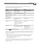
CANopen DS 301 Implementation Guide Manufacturer-specific Objects MAN-CAN301IG (Ver. 2.1) The following table lists the values used to define the digital input transitions: DIN Mask Value DIN Logic Level for Activating an Event 0 No event occurs. 1 Switched from low to high (↑). 2 Switched from high to low (↓). 3 Switched (↑ or ↓). When a DIN event occurs, the mapped TPDO is transmitted. The DIN mask value is determined according to a 2-bit field of the digital input.
CANopen DS 301 Implementation Guide Manufacturer-specific Objects MAN-CAN301IG (Ver. 2.1) Entry description: Access Read/Write PDO mapping No Value range 0x0FFF Default value 0x0FFF (event on every switch) Object 0x2F30: Last time stamp correction This object reads the difference between the last Sync time and the last Time Stamp. It serves to estimate how accurately the internal drive clock is locked onto the master clock.
CANopen DS 301 Implementation Guide Manufacturer-specific Objects MAN-CAN301IG (Ver. 2.1) Object description: Index 2F31h Name Last SYNC time Object code VAR Data type UNSIGNED32 Category Entry description: Access Read only PDO mapping No Value range No Default value 0 Object 0x2F40: Configuration object This bit field object gives several configuration options to the drive.
CANopen DS 301 Implementation Guide Manufacturer-specific Objects MAN-CAN301IG (Ver. 2.1) Object 0x2F41: DS402 Configuration object This bit field object gives several configuration options to the DS402 protocol. It resets to 0 after boot reset and must be set again in such cases.
CANopen DS 301 Implementation Guide Manufacturer-specific Objects MAN-CAN301IG (Ver. 2.1) Object 0x2F60 – Zero torque threshold In the DS402 profile torque, it is necessary to define a window around the target torque ‘0’, to obtain a good indication of when the target is reached. By default, this window is 5% of the Current Limit (CL [1]). It is possible to modify the percentage by means of this object. Defines the '0' torque (current) for profile torque 'target reached' indication.
CANopen DS 301 Implementation Guide Manufacturer-specific Objects MAN-CAN301IG (Ver. 2.1) • Entry description: Access Read/write PDO mapping No Value range UNSIGNED16 Default value No Note: In the situation where the torque command value is not set to '0', a default threshold of 25%is used. Object 0x2F70 – CAN Encoder Range This object defines the range of the CAN Encoder. The low limit is stored in sub-index 1 and the high limit in sub-index 2.
CANopen DS 301 Implementation Guide Manufacturer-specific Objects MAN-CAN301IG (Ver. 2.1) Sub-index 1 Description Low Limit Entry category Optional Access Read/write PDO mapping No Value range INTEGER32 Default value No Sub-index 2 Description Hi Limit Entry category Optional Access Read/write PDO mapping No Value range INTEGER32 Default value No Note: This object is applicable to special FW versions.
CANopen DS 301 Implementation Guide Error Control Protocol MAN-CAN301IG (Ver. 2.1) Chapter 14: Error Control Protocol For node guarding and life guarding, SimplIQ digital servo drives implement the heartbeat mechanism, as defined by CiA DS 301, version 4.0. With this process, a CAN slave can monitor other devices to determine if they are active, according to their periodic heartbeat messages. The CAN slave can send heartbeats to consumers, which may want to monitor if this slave is active.
CANopen DS 301 Implementation Guide Downloading Firmware MAN-CAN301IG (Ver. 2.1) Chapter 15: Downloading Firmware New firmware versions can be loaded via CAN communications by writing the new firmware as S-records to object 0x2090. The S-records are written as string SDOs to object 0x2090. After the firmware is downloaded, the drive continues to communicate using the previous firmware. If the download fails, a retry is possible.
CANopen DS 301 Implementation Guide Initial CAN Communication Setup MAN-CAN301IG (Ver. 2.1) Chapter 16: Initial CAN Communication Setup 16.1 Setup Using RS-232 All communication parameters — such as the CAN baud rate for the targets — are programmed via the PP[N] command. In order to program the communication parameters, communication must first be established with the servo drive, so that the RS-232 communication channel, which is always active, can be used.
CANopen DS 301 Implementation Guide Appendix: Little and Big Endians MAN-CAN301IG (Ver. 2.1) 16.2 Bootup Protocol This protocol is used to signal that an NMT slave has entered the pre-operational node state after the initializing state. The protocol uses the same identifier as the error control protocols. NMT Master COB-ID = 1792 + Node-ID 0 1 0 indication Heartbeat Consumer(s) indication One data byte is transmitted with value 0.
CANopen DS 301 Implementation Guide Initial CAN Communication Setup MAN-CAN301IG (Ver. 2.1) Appendix A: Little and Big Endians The “end” in “endians” refers to the address of the most significant or least significant byte in a multiple-byte data type (such as short, long or float). The address of big endians is the most significant byte (the “big” end) while the address of little endians is the least significant byte (the “little” end).