Eagle Digital Servo Drive Installation Guide July 2014 (Ver. 1.902) www.elmomc.
Notice This guide is delivered subject to the following conditions and restrictions: • This guide contains proprietary information belonging to Elmo Motion Control Ltd. Such information is supplied solely for the purpose of assisting users of the Eagle servo drive in its installation. • The text and graphics included in this manual are for the purpose of illustration and reference only. The specifications on which they are based are subject to change without notice.
Revision History Version Date Details 1.0 June 2007 Initial release 1.1 April 2008 Updated Power Ratings Table in Chapter 4 (Appendix) 1.2 May 2008 Following sections added: 3.4.2.2 Connecting the DC Power; 3.5 DC Power Supply; 3.6 Heat Dissipation 1.3 December 2008 MTCR 00-100-30: Auxiliary power supply is mandatory for Eagle XX/400 drives 1.4 May 2009 MTCR 05-009-54: Section 3.4.2.2.a: Expanded the XX/400 note; Section 4.3: Added auxiliary power data for EAG 18/400. 1.
Elmo Worldwide Head Office Elmo Motion Control Ltd. 60 Amal St., P.O. Box 3078, Petach Tikva 49516 Israel Tel: +972 (3) 929-2300 • Fax: +972 (3) 929-2322 • info-il@elmomc.com North America Elmo Motion Control Inc. 42 Technology Way, Nashua, NH 03060 USA Tel: +1 (603) 821-9979 • Fax: +1 (603) 821-9943 • info-us@elmomc.com Europe Elmo Motion Control GmbH Hermann-Schwer-Strasse 3, 78048 VS-Villingen Germany Tel: +49 (0) 7721-944 7120 • Fax: +49 (0) 7721-944 7130 • info-de@elmomc.
Eagle Installation Guide MAN-EAGIG (Ver. 1.902) Table of Contents Chapter 1: 1.1. 1.2. 1.3. 1.4. 1.5. Warnings......................................................................................................................... 9 Cautions .......................................................................................................................... 9 Directives and Standards ..............................................................................................
Eagle Installation Guide Table of Contents MAN-EAGIG (Ver. 1.902) 3.5. 3.6. 3.4.6.4. Pulse-and-Direction Input Option on Feedback B (YA[4]=0) ........ 54 3.4.7. I/O Cables ...................................................................................................... 58 3.4.7.1. General I/O Port (J3) ..................................................................... 58 3.4.8. Communication Cables .................................................................................. 60 3.4.8.1.
Eagle Installation Guide Table of Contents MAN-EAGIG (Ver. 1.902) 4.5. 4.6. 4.7. 4.8. 4.4.3. Auxiliary Port ................................................................................................. 82 I/Os ............................................................................................................................... 83 4.5.1. Digital Input Interfaces .................................................................................. 83 4.5.2. Digital Output Interface ............
Eagle Installation Guide 8 MAN-EAGIG (Ver. 1.902) Chapter 1: Safety I nform ation In order to achieve the optimum, safe operation of the Eagle servo drives, it is imperative that you implement the safety procedures included in this installation guide. This information is provided to protect you and to keep your work area safe when operating the Eagle as well as the accompanying equipment. Please read this chapter carefully before you begin the installation process.
Eagle Installation Guide Safety Information MAN-EAGIG (Ver. 1.902) 1.1. Warnings • To avoid electric arcing and hazards to personnel and electrical contacts, never connect/disconnect the servo drive while the power source is on. • Power cables can carry a high voltage, even when the motor is not in motion. Disconnect the Eagle from all voltage sources before it is opened for servicing. • The Eagle servo drives contain grounding conduits for electric current protection.
Safety Information Eagle Installation Guide MAN-EAGIG (Ver. 1.902) 1.3.
Eagle Installation Guide Safety Information MAN-EAGIG (Ver. 1.902) 1.4. CE Marking Conformance The Eagle servo drives are intended for incorporation in a machine or end product. The actual end product must comply with all safety aspects of the relevant requirements of the European Safety of Machinery Directive 98/37/EC as amended, and with those of the most recent versions of standards EN60204-1 and EN292-2 at the least.
Eagle Installation Guide 12 MAN-EAGIG (Ver. 1.902) Chapter 2: Product Description This installation guide describes the Eagle servo drives and the steps for its wiring, installation and power-up. Following these guidelines ensures maximum functionality of the drive and the system to which it is connected. 2.1. Ex trI Q Product Family Elmo Motion Control’s ExtrIQ product family is a set of durable motion control products for applications operating under extreme environmental conditions.
Eagle Installation Guide Product Description MAN-EAGIG (Ver. 1.902) Based on Elmo Motion Control's innovative ExtrIQ core technology, they support a wide range of motor feedback options, programming capabilities and communication protocols. 2.2. Drive Description The Eagle series are highly resilient digital servo drives designed to deliver the highest density of power and intelligence. The Eagle delivers up to 9.6 kW of continuous power or 15.8 kW of peak power in a compact package.
Eagle Installation Guide Product Description MAN-EAGIG (Ver. 1.902) 2.3. Product Features 2.3.1. Current Control • Fully digital • Sinusoidal commutation with vector control or trapezoidal commutation with encoder and/or digital Hall sensors • 12-bit current loop resolution • Automatic gain scheduling, to compensate for variations in the DC bus power supply 2.3.2.
Eagle Installation Guide Product Description MAN-EAGIG (Ver. 1.902) 2.3.5.
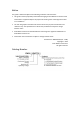
Eagle Installation Guide Product Description MAN-EAGIG (Ver. 1.902) 2.4. System Architecture 24 VDC Main 12 to 390 VDC Power Supply Figure 1: Eagle System Block Diagram 2.5. How to Use this Guide In order to install and operate your Elmo Eagle servo drives, you will use this manual in conjunction with a set of Elmo documentation.
Eagle Installation Guide Product Description MAN-EAGIG (Ver. 1.902) Figure 2: Elmo Digital Servo Drive Documentation Hierarchy As depicted in the previous figure, this installation guide is an integral part of the Eagle documentation set, comprising: • The Composer Software Manual, which includes explanations of all the software tools that are part of Elmo’s Composer software environment.
Eagle Installation Guide 18 MAN-EAGIG (Ver. 1.902) Chapter 3: I nstallation The Eagle must be installed in a suitable environment and properly connected to its voltage supplies and the motor. 3.1. Before You Begin 3.1.1. Site Requirements You can guarantee the safe operation of the Eagle by ensuring that it is installed in an appropriate environment.
Installation Eagle Installation Guide MAN-EAGIG (Ver. 1.902) Component Connector Described in Section Main and Auxiliary Feedbacks Cable Feedback A and Feedback B Digital I/O and Analog Input Cable (if needed) GENERAL I/O J1 3.4.7.1 RS232 Communication Cable RS232 3.4.8.1 CAN Communication cable(s) (if needed) CAN (in), CAN (out) and Backup Option 3.4.8.2 19 Diagram 3.4.4 PC for drive setup and tuning Motor data sheet or manual www.elmomc.
Installation Eagle Installation Guide MAN-EAGIG (Ver. 1.902) 3.2. 20 Unpacking the Drive Components Before you begin working with the Eagle system, verify that you have all of its components, as follows: • The Eagle servo drive • The Composer software and software manual The Eagle is shipped in a cardboard box with styrofoam protection. To unpack the Eagle: 1. Carefully remove the servo drive from the box and the Styrofoam. 2.
Installation Eagle Installation Guide MAN-EAGIG (Ver. 1.902) 3.3. 21 Mounting the Eagle The Eagle has been designed for mounting on a flat surface. M5 round head screws, one through each opening in the heat sink, are used to mount the Eagle (see the diagram below). Figure 3: Mounting the Eagle www.elmomc.
Eagle Installation Guide Installation MAN-EAGIG (Ver. 1.902) 3.4. 22 Connecting the Cables The Eagle has five power screw connectors, four holes for ground connections, and four D-Sub type connectors. 3.4.1. Wiring the Eagle Once the Eagle is mounted, you are ready to wire the device. Proper wiring, grounding and shielding are essential for ensuring safe, immune and optimal servo performance of the Eagle.
Installation Eagle Installation Guide MAN-EAGIG (Ver. 1.
Eagle Installation Guide MAN-EAGIG (Ver. 1.902) Installation 24 Figure 4: Eagle Detailed Connection Diagram www.elmomc.
Installation Eagle Installation Guide MAN-EAGIG (Ver. 1.902) 3.4.2. 25 Connecting the Power Cables The V bus and motor power screws are located in the lower part of the Eagle and include the following: Pin Function Cable Pin Positions VP+ Pos. Power input Power VN- Neg.
Installation Eagle Installation Guide MAN-EAGIG (Ver. 1.902) 26 M6 nut (available with the drive) M6 spring washer M5 screw Barrel connector M5 spring washer Barrel connector M5 flat washer Step 1: PE Connection M5 screw M5 spring washer Barrel connector M5 flat washer www.elmomc.
Eagle Installation Guide Installation MAN-EAGIG (Ver. 1.902) 27 Step 2: Power and Motor Connection M6 nut (available with the drive) M6 spring washer Barrel connector Table 5: Connecting the Main Power and Motor Cables 3.4.2.1. Connecting the Motor Cable Connect the motor power cable to the M1, M2, and M3 terminals of the main power connector and the fourth wire to the PE (Protective Earth) on the heat sink (see diagram above).
Installation Eagle Installation Guide MAN-EAGIG (Ver. 1.902) 28 Figure 5: AC Motor Power Connection Diagram 3.4.2.2. Connecting the DC Power The Power stage of the Eagle is fully isolated from other sections of the Eagle, such as the control stage and the heat sink. This contributes very significantly to the safety and the EMI immunity of the Eagle.
Eagle Installation Guide Installation MAN-EAGIG (Ver. 1.902) 3.4.2.2.b 29 Operation with an Isolated Battery Power Supply Figure 7: Isolated Battery Power Supply Caution: When using batteries, it is recommended to connect the negative pole to the PE. When doing so, the charger of the battery must be isolated from the mains by an isolation transformer. 3.4.2.2.
Installation Eagle Installation Guide MAN-EAGIG (Ver. 1.902) 3.4.2.2.d 30 Operation with a Non-Isolated DC Power Supply by Auto Transformer Figure 9: Non-Isolated DC Power Supply by Auto Transformer The Power Supply is directly connected to the AC line through an Autotransformer. The network PE must not be connected to the Return of the Power Supply.
Installation Eagle Installation Guide MAN-EAGIG (Ver. 1.902) 3.4.2.3. 31 Connecting the Optional Backup Supply Cable Power to the Eagle is provided by a 12 to 195 VDC source (depending on the model type). With the exception of the Eagle XX/400 model, a “smart” control-supply algorithm enables the Eagle to operate with only one power supply with no need for an auxiliary supply voltage.
Eagle Installation Guide Installation MAN-EAGIG (Ver. 1.902) 32 Figure 10: Backup Supply Connection Diagram The Eagle provides the following smart control supply options: • Internal DC-to-DC converter that allows operation from DC power (no need for auxiliary external supply for normal operation) • 12 to 195 VDC supply for backing up the control parameters if DC power is shut off www.elmomc.
Installation Eagle Installation Guide MAN-EAGIG (Ver. 1.902) 3.4.3. 33 Feedback Control and Communication Cable Assemblies The Eagle features easy-to-use D-Sub type connections for all Control and Feedback cables. Instructions and diagrams describing how to assemble those cables are presented below. 1. Use 24, 26 or 28 AWG twisted-pair shielded cables (24 AWG cable is recommended). For best results, the shield should have aluminum foil covered by copper braid. 2.
Installation Eagle Installation Guide MAN-EAGIG (Ver. 1.902) 34 Feedback A on the “front” of the Eagle has a 26-pin high density D-Sub socket. Connect the Main Feedback cable from the motor to Feedback A using a 26-pin, high density D-Sub plug with a metal housing. When assembling the Main Feedback cable, follow the instructions in Section 3.4.3 (Feedback Control and Communication Cable Assemblies). Note: The Feedback connector also supports Feedbacks A and B.
Installation Eagle Installation Guide MAN-EAGIG (Ver. 1.902) Incremental Encoder Interpolated Analog Encoder Resolver 35 Tachometer and Potentiometer output 11 B2 – Aux. CHAOOutput Aux./Main channel A low output CHAO- Aux./ Emulated CHAOchannel A low output Aux./ CHAOEmulated channel A low output Aux./ Emulated channel A low output 12 B2 – Aux. CHBO Output Aux./Main channel B high output CHBO Aux./ Emulated CHBO channel B high output CHBO Aux./ Emulated channel B high output Aux.
Installation Eagle Installation Guide MAN-EAGIG (Ver. 1.902) Incremental Encoder 21 B1 – Aux. Input/ Output CHB Main channel CHB B high output/ Auxiliary channel B high input Incremental Encoder Pin 22 23 24 25 26 Port B1 – Aux. Input/ Output B1 – Aux. Input/ Output B1 – Aux.
Installation Eagle Installation Guide MAN-EAGIG (Ver. 1.902) 37 Absolute Encoders EAG-XX/YYYQ Pin Port Signal Heidenhain 2.
Installation Eagle Installation Guide MAN-EAGIG (Ver. 1.902) 38 Absolute Encoders EAG-XX/YYYQ Pin 22 Port Signal Heidenhain 2.1 Signal B1– Aux. CHBInput/ Output Emulated channel B low output/ 23 B1– Aux. INDEX Input/ Output Auxiliary INDEX high input INDEX Auxiliary INDEX high input 24 B1– Aux.
Eagle Installation Guide Installation MAN-EAGIG (Ver. 1.902) 39 Figure 13: Main Feedback – Interpolated Analog (Sine/Cosine) Encoder Connection Diagram Figure 14: Main Feedback – Resolver Connection Diagram www.elmomc.
Eagle Installation Guide Installation MAN-EAGIG (Ver. 1.902) 40 Figure 15: Main Feedback – Tachometer Feedback with Digital Hall Sensor Connection Diagram for Brushless Motors Figure 16: Main Feedback – Tachometer Feedback Connection Diagram for Brush Motors www.elmomc.
Eagle Installation Guide Installation MAN-EAGIG (Ver. 1.902) 41 Figure 17: Main Feedback – Potentiometer Feedback with Digital Hall Sensor Connection Diagram for Brushless Motors Figure 18: Main Feedback – Potentiometer Feedback Connection Diagram for Brush Motors and Voice Coils www.elmomc.
Eagle Installation Guide Installation MAN-EAGIG (Ver. 1.902) 42 Figure 19: Main Feedback – Heidenhain (EnDat 2.1) Feedback with Hall Sensor Connection Diagram www.elmomc.
Eagle Installation Guide MAN-EAGIG (Ver. 1.902) Installation 43 Figure 20: Main Feedback – Heidenhain (EnDat 2.1) Feedback Connection Diagram www.elmomc.
Eagle Installation Guide Installation MAN-EAGIG (Ver. 1.902) 44 Figure 21: Main Feedback – Stegmann (Hiperface) Feedback with Hall Sensor Connection Diagram www.elmomc.
Eagle Installation Guide Installation MAN-EAGIG (Ver. 1.902) 45 Figure 22: Main Feedback – Stegmann (Hiperface) Feedback Connection Diagram www.elmomc.
Installation Eagle Installation Guide 46 MAN-EAGIG (Ver. 1.902) 3.4.5. Main and Auxiliary Feedback Combinations The Main Feedback is always used in motion control devices whereas Auxiliary Feedback is often, but not always used. The Auxiliary Feedback connector on the Eagle, “Feedback B” has two ports, Port B1 and Port B2.
Installation Eagle Installation Guide MAN-EAGIG (Ver. 1.902) Feedback A Feedback B Ports B1 and B2 YA[4] = 4 Software Setting Potentiometer Input YA[4] = 2 Potentiometer Position Data Emulated in Incremental Encoder Format (signals are quadrature, differential & buffered) B2- Output same as B1 Any application where the main encoder is used, not only for the drive, but also for other purposes such as position controllers and/or other drives.
Installation Eagle Installation Guide MAN-EAGIG (Ver. 1.902) 3.4.6.1. 48 Main Encoder Buffered Outputs or Emulated Encoder Outputs Option on Feedback B (YA[4]=4) Through Feedback B (Ports B1 and B2) the Eagle can provide two simultaneous buffered main, or emulated, encoder signals to other controllers or drives. This option can be used when: • The Eagle is used as a current amplifier to provide position data to the position controller.
Eagle Installation Guide Installation MAN-EAGIG (Ver. 1.902) 49 Note: In models not containing absolute encoder support, it is possible to use terminals 16 and 17 for SUPRET connections. Feedback B on the “top” of the Eagle has a 26-pin high density D-Sub socket. Connect the Auxiliary Feedback cable, from the controller or other device, to Feedback B using a 26-pin, high density DSub plug with a metal housing. When assembling the Auxiliary Feedback cable, follow the instructions in Section 3.4.
Installation Eagle Installation Guide MAN-EAGIG (Ver. 1.902) 3.4.6.2. 50 Differential Auxiliary Encoder Input Option on Feedback B (YA[4]=2) The Eagle can be used as a slave by receiving the position of the master encoder data (on Port B1) in Follower or ECAM mode. In this mode Port B2 provides differential buffered auxiliary outputs for the next slave axis in follower or ECAM mode.
Eagle Installation Guide Installation MAN-EAGIG (Ver. 1.902) 51 Feedback B on the “top” of the Eagle has a 26-pin high density D-Sub socket. Connect the Auxiliary Feedback cable from the feedback device to Feedback B using a 26-pin, high density D-Sub plug with a metal housing. When assembling the Auxiliary Feedback cable, follow the instructions in Section 3.4.3 (Feedback Control and Communication Cable Assemblies).
Installation Eagle Installation Guide MAN-EAGIG (Ver. 1.902) 3.4.6.3. 52 Single-Ended Auxiliary Input Option on Feedback B (YA[4]=2) The Eagle can be used as a slave by receiving the position data (on Port B1) of the master encoder in Follower or ECAM mode. In this mode Port B2 provides differential buffered auxiliary outputs for the next slave axis in Follower or ECAM mode.
Eagle Installation Guide Installation MAN-EAGIG (Ver. 1.902) 53 with a metal housing. When assembling the Auxiliary Feedback cable, follow the instructions in Section 3.4.3 (Feedback Control and Communication Cable Assemblies). Figure 25: Single-Ended Auxiliary Input Option on Feedback B – Connection Diagram www.elmomc.
Installation Eagle Installation Guide MAN-EAGIG (Ver. 1.902) 3.4.6.4. 54 Pulse-and-Direction Input Option on Feedback B (YA[4]=0) This mode is used for input of differential or single-ended pulse-and-direction position commands on Port B1. In this mode Port B2 provides differential buffered pulse-and-direction outputs for another axis.
Eagle Installation Guide MAN-EAGIG (Ver. 1.902) Installation 55 Figure 26: Single-Ended Pulse-and-Direction Input Option on Feedback B – Connection Diagram www.elmomc.
Eagle Installation Guide Installation MAN-EAGIG (Ver. 1.902) 56 Below are the signals on the Auxiliary Feedback ports when set up to run as a differential pulseand-direction input: Port Pin Signal Function B2 10 CHAO Channel A output B2 11 CHAO- Channel A complement output B2 12 CHBO Channel B output.
Eagle Installation Guide Installation MAN-EAGIG (Ver. 1.902) 57 Figure 27: Differential Pulse-and-Direction Input Option on Feedback B - Connection Diagram www.elmomc.
Installation Eagle Installation Guide MAN-EAGIG (Ver. 1.902) 3.4.7. 58 I/O Cables The Eagle has one I/O port, J3. J3 is a general I/O, which can be used to connect 6 digital inputs, 2 digital outputs and 1 analog input. 3.4.7.1. I/O J3 Port Digital Input 6 Digital Output 2 Analog Input 1 General I/O Port (J3) Port J3 has a 15-pin high density D-Sub plug. When assembling this I/O cable, follow the instructions in Section 3.4.
Eagle Installation Guide MAN-EAGIG (Ver. 1.902) Installation 59 Figure 28: General J1 I/O Connection Diagram www.elmomc.
Installation Eagle Installation Guide MAN-EAGIG (Ver. 1.902) 3.4.8. 60 Communication Cables The communication cables use a 9-pin D-Sub plug that connect to the RS-232 and 9-pin D-Sub socket that connects to the CAN ports on the Eagle. The communication interface may differ according to the user’s hardware. The Eagle can communicate using the following options: a. RS-232, full duplex b.
Installation Eagle Installation Guide MAN-EAGIG (Ver. 1.902) 61 Figure 29: RS-232 Connection Diagram 3.4.8.2. CAN Communication Notes for connecting the CAN communication cable: • Use 24, 26 or 28 AWG twisted pair shielded cables (24 AWG cable is recommended). For best results, the shield should have aluminum foil and covered by copper braid with a drain wire • Connect the shield to the ground of the host (PC). Usually, this connection is soldered internally inside the connector at the PC end.
Installation Eagle Installation Guide MAN-EAGIG (Ver. 1.902) 62 Caution: When installing CAN communications, ensure that each servo drive is allocated a unique ID. Otherwise, the CAN network may Figure 30: CAN Connection Diagram www.elmomc.
Eagle Installation Guide Installation MAN-EAGIG (Ver. 1.902) 3.5. 63 DC Power Supply The DC power supply can be at any voltage in the range defined in the technical specifications (see the Appendix of this manual). The supply source must comply with the safety aspects of the relevant requirements, in accordance with the most recent version of the standard EN 60950 or equivalent Low Voltage Directive Standard, all according to the applicable overvoltage category.
Eagle Installation Guide Installation MAN-EAGIG (Ver. 1.902) 3.6. 64 Heat Dissipation For full power output capability the Eagle is designed to be mounted on an external heat sink. It is highly recommended that the “Wall” on which the Eagle is mounted will have heat dissipation capabilities. The Eagle at “free air convection” (without an additional heat sink) can dissipate around 12 W for 40 °C ambient temperature and not exceeding 80 °C on the heat sink.
Installation Eagle Installation Guide MAN-EAGIG (Ver. 1.902) 3.6.2. 65 Heat Dissipation Data Heat Dissipation is shown in graphically below: Power Dissipation 60V series 100 90 80 Power Dissipation (W) 70 12VDC 20VDC 30VDC 40VDC 50VDC 56VDC 60 50 40 30 20 10 0 0 12 20 30 40 50 60 70 80 90 Motor's Current (Ampere) www.elmomc.
Installation Eagle Installation Guide MAN-EAGIG (Ver. 1.902) 66 Power Dissipation 100V series 120 Power Dissipation (W) 100 80 20VDC 40VDC 60VDC 80VDC 96VDC 60 40 20 0 0 8.3 16.7 25.0 33.3 41.7 50.0 58.3 66.7 75.0 Motor's Current (Ampere) Power Dissipation 200V series 250 Power Dissipation (W) 200 40VDC 80VDC 120VDC 160VDC 196VDC 150 100 50 0 0 6.7 13.3 20.0 26.7 33.3 40.0 46.7 53.3 60.0 Motor's Current (Ampere) www.elmomc.
Eagle Installation Guide Installation MAN-EAGIG (Ver. 1.902) 3.6.3. 67 How to Use the Charts The charts above are based upon theoretical worst-case conditions. Actual test results show 30% 50% better power dissipation. To determine if your application needs a heat sink: 1. Allow maximum heat sink temperature to be 80°C or less (shunt down is 6 °C to 8 °C higher). 2. Determine the ambient operating temperature of the Eagle as ≤ 40 °C. 3.
Eagle Installation Guide 68 MAN-EAGIG (Ver. 1.902) Chapter 4: Technical Specifications This chapter provides detailed technical information regarding the Eagle. This includes its dimensions, power ratings, the environmental conditions under which it can be used, the standards to which it complies and other specifications. 4.1. Features The Eagle's features determine how it controls motion, as well as how it processes host commands, feedback and other input. 4.1.1.
Eagle Installation Guide Technical Specifications MAN-EAGIG (Ver. 1.902) 4.1.5.
Eagle Installation Guide Technical Specifications MAN-EAGIG (Ver. 1.902) • Two programmable Digital Outputs, optically isolated (open, emitter and collector) Brake Control Amplifier fault indication General-purpose Servo enable indication • Differential emulated outputs of the resolver, interpolated analog encoder, tachometer and absolute encoder • Fast output compare (OC), optically isolated • Pulse and Direction inputs (single-ended and differential) • PWM current command output 4.1.
Eagle Installation Guide Technical Specifications MAN-EAGIG (Ver. 1.902) 4.1.9. Automatic Procedures • Commutation alignment • Phase sequencing • Current loop offset adjustment • Current loop gain tuning • Current gain scheduling • Velocity loop offset adjustment • Velocity gain tuning • Velocity gain scheduling • Position gain tuning 4.2. Dimensions www.elmomc.
Technical Specifications Eagle Installation Guide MAN-EAGIG (Ver. 1.902) 4.3.
Technical Specifications Eagle Installation Guide MAN-EAGIG (Ver. 1.902) 4.1.
Technical Specifications Eagle Installation Guide MAN-EAGIG (Ver. 1.902) 4.2.
Technical Specifications Eagle Installation Guide MAN-EAGIG (Ver. 1.902) 4.3. Control Specifications 4.3.1.
Technical Specifications Eagle Installation Guide MAN-EAGIG (Ver. 1.902) 4.3.2.
Technical Specifications Eagle Installation Guide MAN-EAGIG (Ver. 1.902) 4.4. Feedbacks The Eagle can receive and process feedback input from diverse types of devices. 4.4.1. Feedback Supply Voltage The Eagle has two feedback ports (main and auxiliary). The drives supply voltage to the main and auxiliary feedback devices (200 mA to the main feedback and 200 mA to the auxiliary feedback).
Technical Specifications Eagle Installation Guide MAN-EAGIG (Ver. 1.902) 4.4.2.2. Digital Halls Feature Details Halls inputs • HA, HB, HC. • Single-ended inputs • Built in hysteresis of 1 V for noise immunity Input voltage Nominal operating range: 0 V < VIn_Hall < 5 V Maximum absolute: -1 V < VIn_Hall < 15 V High level input voltage: V InHigh > 2.5 V Low level input voltage: V InLow < 1 V Input current Sink current (when input pulled to the common): 3 mA Maximum frequency fMAX : 2 kHz 4.4.2.3.
Technical Specifications Eagle Installation Guide MAN-EAGIG (Ver. 1.902) 4.4.2.4. Resolver Feature Details Resolver format • Sine/Cosine • Differential Input resistance Differential 2.49 kΩ Resolution Programmable: 10 to 15 bits Maximum electrical frequency (RPS) 512 revolutions/sec Resolver transfer ratio 0.
Technical Specifications Eagle Installation Guide MAN-EAGIG (Ver. 1.902) 4.4.2.6. Potentiometer Feature Details Potentiometer Format Single-ended Operating Voltage Range 0 to 5 V supplied by the Eagle Potentiometer Resistance 100 Ω to 1 kΩ … above this range, linearity is affected detrimentally Input Resistance 100 kΩ Resolution 14 bit 4.4.2.7. Absolute Encoder Feature Details Analog encoder format Sine and Cosine signals Analog input signal level • Offset voltage: 2.2 V – 2.
Technical Specifications Eagle Installation Guide MAN-EAGIG (Ver. 1.902) 4.4.2.8.
Technical Specifications Eagle Installation Guide MAN-EAGIG (Ver. 1.902) 4.4.3.
Eagle Installation Guide Technical Specifications MAN-EAGIG (Ver. 1.902) 4.5. I/Os The Eagle has: • • • 6 Digital Inputs 2 Digital Outputs 1 Analog Input 4.5.1. Digital Input Interfaces Feature Type of input Details Connector Location • Optically isolated • Single-ended • PLC level Input current * Iin = 2.2 mA for Vin = 12 V * Iin = 4.4 mA for Vin = 12 V 12 V < Vin < 30 V, 24 V typical Low-level input voltage 0 V < Vin < 6.
Eagle Installation Guide Technical Specifications MAN-EAGIG (Ver. 1.902) 4.5.2. Digital Output Interface Feature Details Type of output Connector Location • Optically isolated • Open collector and open emitter Maximum supply output (VCC) 30 V Max. output current Iout (max) (Vout = Low) Iout (max) ≤ 15 mA VOL at maximum output voltage (low level) Vout (on) ≤ 0.3 V + 0.02 * Iout (mA) RL The external resistor RL must be selected to limit the output current to no more than 15 mA.
Technical Specifications Eagle Installation Guide MAN-EAGIG (Ver. 1.902) 4.6. Communications Specification Details RS-232 Signals: • RxD , TxD , GND • Full duplex, serial communication for setup and control • Baud Rate of 9,600 to 57,600 bit/sec CAN CAN bus Signals: • CAN_H, CAN_L, CAN_GND • Maximum Baud Rate of 1 Mbit/sec Version: • DS 301 V4.01 Device Profile (drive and motion control): • DS 402 4.7.
Technical Specifications Eagle Installation Guide MAN-EAGIG (Ver. 1.902) 4.8. Compliance with Standards Specification Details Quality Assurance ISO 9001:2008 Quality Management Design Approved IEC/EN 61800-5-1, Safety Printed wiring for electronic equipment (clearance, creepage, spacing, conductors sizing, etc.) MIL-HDBK- 217F Reliability prediction of electronic equipment (rating, de-rating, stress, etc.
Technical Specifications Eagle Installation Guide MAN-EAGIG (Ver. 1.