Gold Hawk Digital Servo Drive Installation Guide July 2014 (Ver. 1.001) www.elmomc.
Notice This guide is delivered subject to the following conditions and restrictions: • This guide contains proprietary information belonging to Elmo Motion Control Ltd. Such information is supplied solely for the purpose of assisting users of the Gold Hawk servo drive in its installation. • The text and graphics included in this manual are for the purpose of illustration and reference only. The specifications on which they are based are subject to change without notice.
Revision History Version Date Details Ver. 1.000 Nov 2013 Initial release Elmo Worldwide Head Office Elmo Motion Control Ltd. 60 Amal St., P.O. Box 3078, Petach Tikva 49516 Israel Tel: +972 (3) 929-2300 • Fax: +972 (3) 929-2322 • info-il@elmomc.com North America Elmo Motion Control Inc. 42 Technology Way, Nashua, NH 03060 USA Tel: +1 (603) 821-9979 • Fax: +1 (603) 821-9943 • info-us@elmomc.
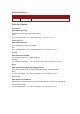
Gold Hawk Installation Guide MAN-G-HAKIG (Ver. 1.001) Table of Contents Chapter 1: 1.1. 1.2. 1.3. 1.4. 1.5. Warnings......................................................................................................................... 8 Cautions .......................................................................................................................... 8 Directives and Standards ................................................................................................
Gold Hawk Installation Guide Table of Contents MAN-G-HAKIG (Ver. 1.001) 4.4. 4.5. 4.6. 4.7. 4.8. 4.9. 4.10. 4.11. 4.12. 4.13. 4.14. 4.3.2.3. Auxiliary Power Connector ........................................................... 25 4.3.2.4. Connector J2 ................................................................................. 26 4.3.2.5. Connector J1 ................................................................................. 29 Mounting the Gold Hawk .....................................
Gold Hawk Installation Guide Table of Contents MAN-G-HAKIG (Ver. 1.001) Chapter 5: 5.1. 5.2. 5.3. 5.4. 5.5. 5.6. 5.7. Dimensions ................................................................................................................... 71 Control Specifications ................................................................................................... 73 5.2.1. Current Loop .................................................................................................. 73 5.2.2.
Gold Hawk Installation Guide 7 MAN-G-HAKIG (Ver. 1.001) Chapter 1: Safety I nform ation In order to achieve the optimum, safe operation of the Gold Hawk servo drive, it is imperative that you implement the safety procedures included in this installation guide. This information is provided to protect you and to keep your work area safe when operating the Gold Hawk and accompanying equipment. Please read this chapter carefully before you begin the installation process.
Gold Hawk Installation Guide Safety Information MAN-G-HAKIG (Ver. 1.001) 1.1. Warnings • To avoid electric arcing and hazards to personnel and electrical contacts, never connect/disconnect the servo drive while the power source is on. • Power cables can carry a high voltage, even when the motor is not in motion. Disconnect the Gold Hawk from all voltage sources before it is opened for servicing. • The Gold Hawk servo drive contains grounding conduits for electric current protection.
Safety Information Gold Hawk Installation Guide MAN-G-HAKIG (Ver. 1.001) 1.3.
Gold Hawk Installation Guide Safety Information MAN-G-HAKIG (Ver. 1.001) 1.4. CE Marking Conformance The Gold Hawk servo drive is intended for incorporation in a machine or end product. The actual end product must comply with all safety aspects of the relevant requirements of the European Safety of Machinery Directive 98/37/EC as amended, and with those of the most recent versions of standards EN 60204-1 and EN 292-2 at the least.
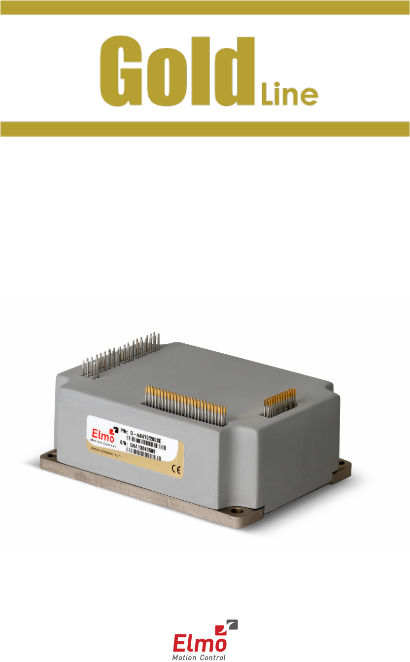
Gold Hawk Installation Guide 11 MAN-G-HAKIG (Ver. 1.001) Chapter 2: Product Description 2.1. Functional Description The Gold Hawk is an advanced high power density servo drive. It provides top servo performance, advanced networking and built in safety, all in a small PCB mountable package. The Gold Hawk has a fully featured motion controller and local intelligence. The Gold Hawk operates from a DC power source.
Gold Hawk Installation Guide Product Description MAN-G-HAKIG (Ver. 1.001) 2.2.2. Supply Input • Single DC Power Supply - Power to the Gold Hawk is provided by a 14 to 195 VDC single isolated DC power source (not included with the Gold Hawk). A “smart” control-supply algorithm enables the Gold Hawk to operate with only one power supply with no need for an auxiliary power supply for the logic. • Optional Backup Supply - If backup functionality is required in case of power loss, e.g.
Gold Hawk Installation Guide Product Description MAN-G-HAKIG (Ver. 1.001) 2.2.4.
Gold Hawk Installation Guide Product Description MAN-G-HAKIG (Ver. 1.001) 2.2.7. • There are Port A and Port B feedback input ports that are flexible and configurable.
Gold Hawk Installation Guide Product Description MAN-G-HAKIG (Ver. 1.001) • Absolute serial encoders: • Supports 1 V PTP Sin/Cos Sin/Cos Frequency: up to 500 kHz Internal Interpolation: up to ×8192 Automatic correction of amplitude mismatch, phase mismatch, signal offset NRZ (Panasonic, Tamagawa, Mitutoyo, etc.) EnDAT 2.
Gold Hawk Installation Guide Product Description MAN-G-HAKIG (Ver. 1.001) 2.2.10. • Safety IEC 61800-5-2, Safe Torque Off (STO) Two STO (Safe Torque Off) inputs Optically isolated TTL Level (5 V logic) Open collector and open emitter • UL 508C recognition • UL 60950 compliance • CE EMC compliance 2.2.11.
Gold Hawk Installation Guide Product Description MAN-G-HAKIG (Ver. 1.001) 2.2.13. Built-In Protection • Software error handling • Abort (hard stops and soft stops) • Status reporting • Protection against: • Shorts between motor power outputs Shorts between motor power outputs and power input/return Failure of internal power supplies Over-heating Continuous temperature measurement.
Gold Hawk Installation Guide Product Description MAN-G-HAKIG (Ver. 1.001) 2.3. System Architecture Figure 1: Gold Hawk System Block Diagram www.elmomc.
Gold Hawk Installation Guide Product Description MAN-G-HAKIG (Ver. 1.001) 2.4. How to Use this Guide In order to install and operate your Elmo Gold Hawk servo drive, you will use this manual in conjunction with a set of Elmo documentation.
Gold Hawk Installation Guide 20 MAN-G-HAKIG (Ver. 1.001) Chapter 3: Technical I nform ation Minimum supply voltage VDC 14 23 Nominal supply voltage VDC 85 170 Maximum supply voltage VDC 95 195 Maximum continuous power output W Efficiency at rated power (at nominal conditions) % Maximum output voltage 1600 2800 4000 1650 2800 20/200 17/200 10/200 Units 50/100 Feature 35/100 Technical Data 20/100 3.1.
Technical Information Gold Hawk Installation Guide MAN-G-HAKIG (Ver. 1.001) 3.1.1. Auxiliary Supply Feature Details Auxiliary power supply Isolated DC source only Auxiliary supply input voltage 14 to 95 VDC (100 V models) 23 to 195 (200 V models) Auxiliary supply input power ≤ 5 VA without external loading ≤ 8 VA with full external loading 3.2.
Gold Hawk Installation Guide 22 MAN-G-HAKIG (Ver. 1.001) Chapter 4: I nstallation The Gold Hawk must be installed in a suitable environment and properly connected to its voltage supplies and the motor. 4.1. Site Requirements You can guarantee the safe operation of the Gold Hawk by ensuring that it is installed in an appropriate environment.
Gold Hawk Installation Guide Installation MAN-G-HAKIG (Ver. 1.001) 3. To ensure that the Gold Hawk you have unpacked is the appropriate type for your requirements, locate the part number sticker on the side of the Gold Hawk. It looks like this: 4. Verify that the Gold Hawk type is the one that you ordered, and ensure that the voltage meets your specific requirements. The part number at the top gives the type designation as follows: www.elmomc.
Installation Gold Hawk Installation Guide MAN-G-HAKIG (Ver. 1.001) 4.3. Connectors The Gold Hawk has nine connectors. 4.3.1. Connector Types Port Pins Type Function Connector Location J2 2x24 1.27 mm pitch 0.41 mm sq Feedbacks, Digital Halls, Analog Inputs, Communications J1 2x12 VL 2x1 VP+ 2x3 PR 2x3 Power input return PE 2x2 Protective earth M1 2x3 Motor power output 1 M2 2x3 Motor power output 2 M3 2x3 Motor power output 3 I/O, LEDs, STO 2 mm pitch 0.
Installation Gold Hawk Installation Guide MAN-G-HAKIG (Ver. 1.001) 4.3.2.2. Main Power For full details see Section 4.7.2.2. Pin Function Cable VP+ Pos. Power input Power PR Power return Power PE Protective earth Power Pin Positions Connector Type: 2 mm pitch 0.51 mm sq Table 4: Connector for Main Power 4.3.2.3. Auxiliary Power Connector For full details see Section 4.7.3.
Installation Gold Hawk Installation Guide MAN-G-HAKIG (Ver. 1.001) 4.3.2.4. Connector J2 Feedback A/B/C, Digital Halls – see Section 4.9. Analog Inputs – see Section 4.9.4. RS-232, EtherCAT, USB – see Section 4.11. Connector Type: 1.27 mm pitch 0.41 mm sq Note regarding the EtherCAT and CAN communication options: The J2 Connector exports all supported communication links.
Installation Gold Hawk Installation Guide MAN-G-HAKIG (Ver. 1.
Installation Gold Hawk Installation Guide MAN-G-HAKIG (Ver. 1.
Installation Gold Hawk Installation Guide MAN-G-HAKIG (Ver. 1.001) 4.3.2.5. Connector J1 I/O, LEDs, STO (safety) For full details on user I/Os, see Section 4.10. For full details on STO, see Section 4.8. Connector Type: 1.27 mm pitch 0.
Installation Gold Hawk Installation Guide MAN-G-HAKIG (Ver. 1.001) Pin (J1) Signal Function 16 OUT1 Programmable output 1 17 OUTRET2 OUT 2 return 18 OUTRET1 OUT 1 return 19 LED2 Bi-color indication output 2 (Cathode) 20 LED1 Bi-color indication output 1 (Anode) 21 OUT4 Programmable output 4 not isolated (3.3V TTL level) 22 OUT3 Programmable output 3 not isolated (3.3V TTL level) 23 COMRET Common return 24 Reserved Reserved Table 7: Connector J1 – I/O, LEDs www.elmomc.
Gold Hawk Installation Guide Installation MAN-G-HAKIG (Ver. 1.001) 4.4. Mounting the Gold Hawk The Gold Hawk was designed for mounting on a printed circuit board (PCB) via 1.27 mm pitch 0.41 mm square pins and 2 mm pitch 0.51 mm square pins. When integrating the Gold Hawk into a device, be sure to leave about 1 cm (0.4") outward from the heat-sink to enable free air convection around the drive. We recommend that the Gold Hawk be soldered directly to the board.
Installation Gold Hawk Installation Guide MAN-G-HAKIG (Ver. 1.001) Figure 3: Gold Hawk External Heat Sink 4.5. Integrating the Gold Hawk on a PCB The Gold Hawk is designed to be mounted on a PCB, either by soldering its pins directly to the PCB or by using suitable socket connectors. Refer to the Gold Line Guitar Design Guide for further information. 4.5.1.
Gold Hawk Installation Guide Installation MAN-G-HAKIG (Ver. 1.001) 2. Digital Inputs: The six digital inputs are optically isolated from the other parts of the Gold Hawk. All six inputs share one return line, INRET. To retain isolation, the Input Return pin and all other conductors on the input circuit must be laid out separately. 3. STO: The two digital STO inputs are optically isolated from the other parts of the Gold Hawk. The two STO inputs share one return line, STO_RET.
Gold Hawk Installation Guide Installation MAN-G-HAKIG (Ver. 1.001) 4.6. The Gold Hawk Connection Diagram Figure 4: The Gold Hawk Connection Diagram www.elmomc.
Installation Gold Hawk Installation Guide MAN-G-HAKIG (Ver. 1.001) 4.7. Main Power, Auxiliary Power and Motor Power The Gold Hawk receives power from main and auxiliary supplies and delivers power to the motor. 4.7.1. Motor Power Note: When connecting several drives to several similar motors, all should be wired in an identical manner. This will enable the same settings to run on all drives.
Installation Gold Hawk Installation Guide MAN-G-HAKIG (Ver. 1.001) Figure 6: DC Brushed Motor Power Connection Diagram 4.7.2. Main Power, Motor Power and Auxiliary Power The Gold Hawk receives power from main and auxiliary supplies and delivers power to the motor. Note: There are multiple voltage ratings of the Gold Guitar (14 V to 195 V), so you must use the correct power supply according to the maximum operating voltage of the Gold Hawk, refer to Chapter 3: Technical Information for more details. 4.
Installation Gold Hawk Installation Guide MAN-G-HAKIG (Ver. 1.001) Figure 7: Brushed Motor Power Connection Diagram Figure 8: DC Brushed Motor Power Connection Diagram 4.7.2.2. Pin Main Power Function Cable VP+ Pos. Power input Power PR Power return Power PE Protective earth Power Pin Positions Connector Type: 2 mm pitch 0.51 mm sq Connect the VP+, PR and PE pins on the Gold Hawk in the manner described in Section 4.5 “Integrating the Gold Hawk on a PCB”.
Installation Gold Hawk Installation Guide MAN-G-HAKIG (Ver. 1.001) Figure 9: Main Power Supply Connection Diagram (no Auxiliary Supply) 4.7.3. Auxiliary Power Supply (Optional) Note: The source of the Auxiliary Supply must be isolated. Connect the VL and PR pins on the Gold Hawk in the manner described in Section 4.5 “Integrating the Gold Hawk on a PCB”.
Installation Gold Hawk Installation Guide MAN-G-HAKIG (Ver. 1.001) 4.7.4. Single Supply A single isolated DC power supply can provide power for both the main power and the Auxiliary (Drive Logic) Supply. The drawing below shows how a single supply is connected. Figure 10: Single Supply for both the Main Power Supply and the Auxiliary Supply 4.7.5. Separate Auxiliary (Backup) Supply Power to the Auxiliary Supply can be provided by a separate Auxiliary Supply.
Gold Hawk Installation Guide Installation MAN-G-HAKIG (Ver. 1.001) 4.7.6. Shared Supply A Main DC Power Supply can be designed to supply power to the drive’s logic as well as to the Main Power (see Figure 10 and the upper portion of Figure 12). If backup functionality is required for continuous operation of the drive’s logic in the event of a main power-out, a backup supply can be connected by implementing “diode coupling” (see the Aux. Backup Supply in Figure 12).
Installation Gold Hawk Installation Guide MAN-G-HAKIG (Ver. 1.001) 4.8. STO (Safe Torque Off) Inputs Activation of Safe Torque Off causes the drive to stop providing power that can cause rotation (or motion in the case of a linear motor) to the motor. This function may be used to prevent unexpected motor rotation (of brushless DC motors) without disconnecting the drive from the power supply. The motor is active only as long as 5 V is provided to both STO1 and STO2.
Gold Hawk Installation Guide Installation MAN-G-HAKIG (Ver. 1.001) Figure 13: STO Input Functionality – Schematic Drawing The figure below is for the TTL level. Figure 14: STO Input Connection – TTL Level www.elmomc.
Gold Hawk Installation Guide Installation MAN-G-HAKIG (Ver. 1.001) The figure below is for PLC. Figure 15: STO Input Connection – PLC www.elmomc.
Installation Gold Hawk Installation Guide MAN-G-HAKIG (Ver. 1.001) 4.9. Feedback Port B Port A Port C Figure 16: Feedback Ports on J2 The Gold Hawk has two configurable motion sensor input ports, namely, Port A and Port B, together with the emulated buffered output Port C. Motion sensors from the motor are controlled from other sources and can be connected to any of the available inputs on Port A or Port B. The software configuration designates a role to each input, e.g.
Installation Gold Hawk Installation Guide MAN-G-HAKIG (Ver. 1.001) 4.9.1. Port A (J2) Port A supports the following sensor inputs: • Digital Hall sensors • Incremental encoder or absolute serial encoder, depending on the specific model Differential pulse-width modulation (PWM) signal input can be connected to port A in the models that support input from an incremental encoder. The PWM signal can be connected to the applicable pair of matching + and – encoder channels and is configurable by software.
Gold Hawk Installation Guide Installation MAN-G-HAKIG (Ver. 1.001) 4.9.1.1. Incremental Encoder Figure 17: Port A Incremental Encoder Input – Recommended Connection Diagram www.elmomc.
Gold Hawk Installation Guide Installation MAN-G-HAKIG (Ver. 1.001) 4.9.1.2. Absolute Serial Encoder Figure 18: Absolute Serial Encoder – Recommended Connection Diagram for Sensors Supporting Data/Clock (e.g., Biss / SSI / EnDAT, etc.) www.elmomc.
Gold Hawk Installation Guide Installation MAN-G-HAKIG (Ver. 1.001) Figure 19: Absolute Serial Encoder – Recommended Connection Diagram for Sensors Supporting Data Line Only (NRZ types, e.g., Panasonic / Mitutoyo / etc.) 4.9.1.3. Hall Sensors Figure 20: Hall Sensors Connection Diagram www.elmomc.
Installation Gold Hawk Installation Guide MAN-G-HAKIG (Ver. 1.001) 4.9.2. Port B (J2) Port B supports any of the following sensors: • Incremental encoder, interpolated analog encoder or analog Hall sensors Or: • Resolver (separate hardware option) Differential PWM signal input can be connected to port B in the models that support input from an incremental encoder. The PWM signal can be connected to the applicable pair of matching + and – encoder channels and is configurable by software.
Gold Hawk Installation Guide Installation MAN-G-HAKIG (Ver. 1.001) 4.9.2.1. Incremental Encoder Figure 21: Port B Incremental Encoder Input – Recommended Connection Diagram www.elmomc.
Gold Hawk Installation Guide Installation MAN-G-HAKIG (Ver. 1.001) 4.9.2.2. Interpolated Analog Encoder Figure 22: Port B - Interpolated Analog Encoder Connection Diagram www.elmomc.
Gold Hawk Installation Guide Installation MAN-G-HAKIG (Ver. 1.001) 4.9.2.3. Resolver Figure 23: Port B – Resolver Connection Diagram 4.9.3. Port C – Emulated Encoder Output (J2) Port C provides emulated encoder output derived from port A or port B feedback inputs, or from internal variables. The output options are: • Port A/B daisy chain (1:1) for incremental encoder • Encoder emulation: Emulate any input sensor, digital or analog, or use to emulate an internal variable such as virtual profiler.
Installation Gold Hawk Installation Guide MAN-G-HAKIG (Ver. 1.
Gold Hawk Installation Guide Installation MAN-G-HAKIG (Ver. 1.001) 4.10. User I/Os The Gold Hawk has six programmable digital inputs (J1), four digital outputs (J1) and one analog input (J2). 4.10.1. Digital Inputs (J1) Each of the pins below can function as an independent input. The inputs conform to the TTL level.
Gold Hawk Installation Guide Installation MAN-G-HAKIG (Ver. 1.001) Figure 25: Digital Input Connection Diagram – TTL Level See the figure below for the PLC connection. www.elmomc.
Gold Hawk Installation Guide Installation MAN-G-HAKIG (Ver. 1.001) Figure 26: Digital Input Connection Diagram – PLC www.elmomc.
Installation Gold Hawk Installation Guide MAN-G-HAKIG (Ver. 1.001) 4.10.2. Digital Outputs (J1) The outputs conform to the TTL level. Pin (J1) Signal Function 16 OUT1 High speed programmable digital output 1, output compare 15 OUT2 High speed programmable digital output 2, output compare 18 OUTRET1 OUT 1 Return 17 OUTRET2 OUT 2 Return Table 16: Digital Output Pin Assignment Figure 27: Digital Output Connection Diagram – TTL Connection www.elmomc.
Installation Gold Hawk Installation Guide MAN-G-HAKIG (Ver. 1.001) 4.10.3. Analog Input Pin (J2) Signal Function 22 ANALOG1+ Analog input 1+ 24 ANALOG1- Analog input 1- 20 ANARET Analog return Table 17: Analog Input Pin Assignment Figure 28: Analog Input with Single-Ended Source www.elmomc.
Installation Gold Hawk Installation Guide MAN-G-HAKIG (Ver. 1.001) 4.11. Communications The communication interface may differ according to the user’s hardware. The Gold Hawk can communicate using the following options: Standard EtherCAT G-GUTXXX/YYYSX G-GUTXXX/YYYEX CAN EtherCAT USB 2.0 USB 2.0 Ethernet RS-232 (TTL Logic Level) RS-232 (TTL Logic Level) Table 18: Gold Hawk Communication Options For ease of setup and diagnostics of CAN communication, RS-232 and CAN may be used simultaneously.
Gold Hawk Installation Guide Installation MAN-G-HAKIG (Ver. 1.001) Figure 29 describes the RS-232 connection diagram: Figure 29: RS-232 Connection Diagram Note that Elmo does not recommend a specific manufacturer. The following is an example of an RS-232 Line Driver/Receiver. The RS-232 Line Driver/Receiver operates with 3.3 V to 5 V VCC Supply. Figure 30: RS-232 – Translator Block Diagram Notes for connecting the RS-232 communication cable: • Connect the shield to the ground of the host (PC).
Installation Gold Hawk Installation Guide MAN-G-HAKIG (Ver. 1.001) 4.11.2. CAN Communication (J2) Note that CAN functionality is not available if you have the EtherCAT version. In order to benefit from CAN communication, the user must have an understanding of the basic programming and timing issues of a CAN network. Notes for connecting the CAN communication cable: • Connect the shield to the ground of the host (PC). Usually, this connection is soldered internally inside the connector at the PC end.
Gold Hawk Installation Guide Installation MAN-G-HAKIG (Ver. 1.001) Figure 31: CAN Network Diagram Caution: When installing CAN communication, ensure that each servo drive is allocated a unique ID. Otherwise, the CAN network may “hang”. www.elmomc.
Installation Gold Hawk Installation Guide MAN-G-HAKIG (Ver. 1.001) 4.11.3. USB 2.0 Communication (J2) The USB network consists of a Host controller and multiple devices. The Gold Hawk is a USB device. Notes for connecting the USB communication cable: • Connect the shield to the ground of the host (PC). Usually, this connection is soldered internally inside the connector at the PC end. You can use the drain wire to facilitate connection.
Installation Gold Hawk Installation Guide MAN-G-HAKIG (Ver. 1.001) 4.11.4. EtherCAT Communication (J2) To use EtherCAT and Ethernet communication with the Gold Hawk, it is required to use an isolation transformer. The most common solution is to use RJ-45 connectors that include transformer isolation. This section describes how to connect the Gold Hawk’s EtherCAT interface using the above mentioned connectors. For other available options, please see Section 4.11.6.
Gold Hawk Installation Guide Installation MAN-G-HAKIG (Ver. 1.001) Figure 33: EtherCAT Connection Schematic Diagram www.elmomc.
Gold Hawk Installation Guide Installation MAN-G-HAKIG (Ver. 1.001) The diagram above ignores line interface for simplicity. When connecting several EtherCAT devices in a network, the EtherCAT master must always be the first device in the network. The output of each device is connected to the input of the next device. The output of the last device may remain disconnected. If redundancy is required, the output of the last device should be connected to the input of the EtherCAT master.
Installation Gold Hawk Installation Guide MAN-G-HAKIG (Ver. 1.001) Pin (J2) Signal Function 26 +3.3V 3.
Gold Hawk Installation Guide Installation MAN-G-HAKIG (Ver. 1.001) 4.11.6. EtherCAT/Ethernet Line Interface Ethernet transceivers require either isolation transformers or capacitor coupling for proper functioning. The Gold Hawk unit does not include such isolation, therefore you must take this into consideration when designing the integration board. In Sections 4.11.4 and 4.11.5, a schematic connection with a standard RJ-45 connector that includes transformer isolation is described.
Installation Gold Hawk Installation Guide MAN-G-HAKIG (Ver. 1.001) 4.14.2. Heat Dissipation Data Heat Dissipation is shown in graphically below: Hawk Hawk www.elmomc.
Gold Hawk Installation Guide Installation MAN-G-HAKIG (Ver. 1.001) 4.14.3. How to Use the Charts The charts above are based upon theoretical worst-case conditions. Actual test results show 30% to 50% better power dissipation. To determine if your application needs a heat-sink: 1. Allow maximum heat-sink temperature to be 80 °C or less. 2. Determine the ambient operating temperature of the Gold Hawk. 3.
Gold Hawk Installation Guide 71 MAN-G-HAKIG (Ver. 1.001) Chapter 5: Technical Specifications This chapter provides detailed technical information regarding the Gold Hawk. This includes its dimensions, power ratings, the environmental conditions under which it can be used, the standards to which it complies and other specifications. 5.1. Dimensions Figure 37: Gold Hawk Dimension www.elmomc.
Gold Hawk Installation Guide Technical Specifications MAN-G-HAKIG (Ver. 1.001) Figure 38: Gold Hawk Pin Dimension Details www.elmomc.
Technical Specifications Gold Hawk Installation Guide MAN-G-HAKIG (Ver. 1.001) 5.2. Control Specifications 5.2.1.
Technical Specifications Gold Hawk Installation Guide MAN-G-HAKIG (Ver. 1.001) 5.2.2.
Technical Specifications Gold Hawk Installation Guide MAN-G-HAKIG (Ver. 1.001) 5.3. Feedbacks 5.3.1. Feedback Supply Voltage The Gold Hawk has two feedback ports (Main and Auxiliary). The Gold Hawk supplies voltage only to the main feedback device and to the auxiliary feedback device if needed Feature Details Encoder supply voltage 5 V ± 5% @ 2 x 200 mA (maximum) 5.3.2. Feedback Options The Gold Hawk can receive and process feedback input from diverse types of devices. 5.3.2.1.
Technical Specifications Gold Hawk Installation Guide MAN-G-HAKIG (Ver. 1.001) 5.3.2.2. Digital Halls Feature Details Hall inputs • HA, HB, HC • Single ended inputs • Built in hysteresis of 1 V for noise immunity Input voltage Nominal operating range: 0 V < VIn_Hall < 5 V Maximum absolute: -1 V < VIn_Hall < 15 V High level input voltage: V InHigh > 2.5 V Low level input voltage: V InLow < 1 V Input current Sink current (when input pulled to the common): 5 mA Maximum frequency fMAX : 4 kHz 5.3.
Technical Specifications Gold Hawk Installation Guide MAN-G-HAKIG (Ver. 1.001) 5.3.2.4. Resolver Feature Details Resolver format • Sine/Cosine • Differential Input resistance Differential 2.49 kΩ Resolution Programmable: 10 to 15 bits Maximum electrical frequency (RPS) 512 revolutions/sec Resolver transfer ratio 0.
Technical Specifications Gold Hawk Installation Guide MAN-G-HAKIG (Ver. 1.001) 5.3.3. Port C Feedback Output Feature Emulated output Details • A, B, Index • Differential Interface Output current capability • RS-422 Maximum output current: IOH (max) = 2 mA High level output voltage: VOH > 3.0 V Minimum output current: IOL = 2 mA Low level output voltage: VOL < 0.
Technical Specifications Gold Hawk Installation Guide MAN-G-HAKIG (Ver. 1.001) 5.4. I/Os The Gold Hawk has: • 6 Digital Inputs • 2 Digital Outputs • 1 Analog Input 5.4.1. Digital Input Interfaces – TTL Mode Feature Details Type of input Optically isolated Input current for all inputs Iin = 3.8 mA @ Vin = 5 V High-level input voltage 2.4 V < Vin < 15 V, 5 V typical Low-level input voltage 0 V < Vin < 0.
Technical Specifications Gold Hawk Installation Guide MAN-G-HAKIG (Ver. 1.001) 5.4.2. Digital Output Interface – TTL Mode There are 2 types of outputs: • OUT1 and OUT2 are optically isolated outputs • OUT3 and OUT4 are TTL 3.3V non isolated outputs 5.4.2.1. OUT1 and OUT2 The following table describes the electrical specification of theOUT1 and OUT2 outputs: Feature Details Type of output • Optically isolated • Source/Sink Maximum supply output (VCC) 30 V Max.
Technical Specifications Gold Hawk Installation Guide MAN-G-HAKIG (Ver. 1.001) 5.4.2.2. OUT3 and OUT4 These outputs are 3.3V TTL outputs. The following table describes the electrical specification of the outputs: Feature Details Type of output 3.3V TTL VOL max (low level) Vout (on) ≤ 0.4 V VOH min (High level) 2.5V Max. output current IoutH (max) 8 mA 5.4.3.
Technical Specifications Gold Hawk Installation Guide MAN-G-HAKIG (Ver. 1.001) 5.5. Safe Torque Off (STO) The Gold Hawk has two STO (Safe Torque Off) inputs. 5.5.1. STO Input Interfaces – TTL Mode Feature Details Type of input Optically isolated Input current for all inputs Iin = 3.8 mA @ Vin = 5 V High-level input voltage 2.4 V < Vin < 15 V, 5 V typical Low-level input voltage 0 V < Vin < 0.8 V Minimum pulse width >3 ms Figure 42: STO Input Schematic 5.6.
Technical Specifications Gold Hawk Installation Guide MAN-G-HAKIG (Ver. 1.001) Specification Details Layer Setting Service and Protocol Support: • DS 305 Device Profile (drive and motion control): • DS 402 EtherCAT • 100base-T • Baud Rate: 100 Mbit/sec • CAT5 Cable • CoE, FoE, EoE Ethernet • 100base-T • Baud Rate: 100 Mbit/sec • CAT5 Cable • UDP, Telnet USB 5.7. • USB 2.
Gold Line Standards Gold Hawk Installation Guide MAN-G-HAKIG (Ver. 1.001) Chapter 6: Gold Line Standards The Gold Hawk servo drive has been developed, produced, tested and documented in accordance with the relevant standards. Elmo Motion Control is not responsible for any deviation from the configuration and installation described in this documentation. Furthermore, Elmo is not responsible for the performance of new measurements or ensuring that regulatory requirements are met. 6.1.
Gold Line Standards Gold Hawk Installation Guide MAN-G-HAKIG (Ver. 1.001) Safe Torque Off (STO) Safety Standard Item The following GOLD LINE system components are covered by Certificate no. Z10 13 08 84596 001 and the report to the certificate, report no. EP85169C. www.elmomc.
Gold Line Standards Gold Hawk Installation Guide MAN-G-HAKIG (Ver. 1.
Gold Line Standards Gold Hawk Installation Guide MAN-G-HAKIG (Ver. 1.001) 6.2. Safety Specification Details The related standards below apply to the performance of the servo drives as stated in the environmental conditions section 3.
Gold Hawk Installation Guide Gold Line Standards MAN-G-HAKIG (Ver. 1.001) 6.4. EtherCAT Conformance EtherCAT Conformance Test – certification www.elmomc.
Gold Line Standards Gold Hawk Installation Guide MAN-G-HAKIG (Ver. 1.001) 6.5. Other Compliant Standards Quality Assurance ISO 9001:2008 Quality Management Design • IPC-D-275 • IPC-SM-782 • IPC-CM-770 Printed wiring for electronic equipment (clearance, creepage, spacing, conductors sizing, etc.) Reliability MIL-HDBK- 217F Reliability prediction of electronic equipment (rating, de-rating, stress, etc.
Gold Line Standards Gold Hawk Installation Guide MAN-G-HAKIG (Ver. 1.001) 6.6. ExtrIQ Series The Gold Hawk is also designed as part of the ExtriQ series drives that support extended environmental conditions described in section 3.2.