
Instruction Manual
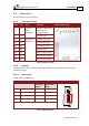
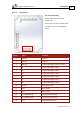
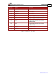
Table Of Contents
- Chapter 1: Safety Information
- Chapter 2: Product Description
- 2.1. Functional Description
- 2.2. Product Features
- 2.2.1. High Power Density
- 2.2.2. Supply Input
- 2.2.3. Servo Control
- 2.2.4. Advanced Filters and Gain Scheduling
- 2.2.5. Motion Control
- 2.2.6. Fully Programmable
- 2.2.7. Feedback Ports Options
- 2.2.8. Feedback Sensor Specifications
- 2.2.9. Communications
- 2.2.10. Safety
- 2.2.11. Outputs
- 2.2.12. Inputs
- 2.2.13. Built-In Protection
- 2.2.14. Status Indication
- 2.2.15. Automatic Procedures
- 2.3. System Architecture
- 2.4. How to Use this Guide
- Chapter 3: Technical Information
- Chapter 4: Installation
- 4.1. Site Requirements
- 4.2. Unpacking the Drive Components
- 4.3. Connectors
- 4.4. Mounting the Gold Hawk
- 4.5. Integrating the Gold Hawk on a PCB
- 4.6. The Gold Hawk Connection Diagram
- 4.7. Main Power, Auxiliary Power and Motor Power
- 4.8. STO (Safe Torque Off) Inputs
- 4.9. Feedback
- 4.10. User I/Os
- 4.11. Communications
- 4.12. Powering Up
- 4.13. Initializing the System
- 4.14. Heat Dissipation
- Chapter 5: Technical Specifications
- Chapter 6: Gold Line Standards

Gold Hawk Installation Guide Installation
MAN-G-HAKIG (Ver. 1.001)
www.elmomc.com
28
Pin (J2) Signal Function
34 EtherCAT: PHY_OUT_TX+ EtherCAT Out transmit
CAN: Reserved Reserved
35 PHY_IN_TX- EtherCAT In transmit complement
36 EtherCAT: PHY_OUT_TX- EtherCAT Out transmit complement
CAN: Reserved Reserved
37 PHY_IN_LINK_ACT EtherCAT In active LED
38 EtherCAT: PHY_OUT_LINK_ACT EtherCAT Out active LED
CAN: CAN_L CAN_L BUS Line(dominant low)
39 PHY_IN_SPEED EtherCAT In Speed LED
40 EtherCAT: PHY_OUT_SPEED EtherCAT Out Speed LED
CAN: CAN_H CAN_H BUS Line(dominant high)
41 USBD- USB data complement
42 USBD+ USB data
43 COMRET Common return
44 USB_VBUS USB VBUS 5V
45 RS232_RX RS232 receive
46 COMRET Common return
47 +5VE Encoder +5 V supply
48 RS232_TX RS232 transmit
Table 6: Connector J2 – Feedback and Analog Input