
Instruction Manual
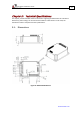
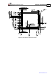
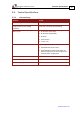
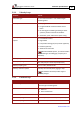
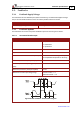
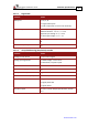
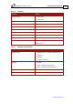
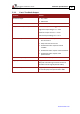
Table Of Contents
- Chapter 1: Safety Information
- Chapter 2: Product Description
- 2.1. Functional Description
- 2.2. Product Features
- 2.2.1. High Power Density
- 2.2.2. Supply Input
- 2.2.3. Servo Control
- 2.2.4. Advanced Filters and Gain Scheduling
- 2.2.5. Motion Control
- 2.2.6. Fully Programmable
- 2.2.7. Feedback Ports Options
- 2.2.8. Feedback Sensor Specifications
- 2.2.9. Communications
- 2.2.10. Safety
- 2.2.11. Outputs
- 2.2.12. Inputs
- 2.2.13. Built-In Protection
- 2.2.14. Status Indication
- 2.2.15. Automatic Procedures
- 2.3. System Architecture
- 2.4. How to Use this Guide
- Chapter 3: Technical Information
- Chapter 4: Installation
- 4.1. Site Requirements
- 4.2. Unpacking the Drive Components
- 4.3. Connectors
- 4.4. Mounting the Gold Hawk
- 4.5. Integrating the Gold Hawk on a PCB
- 4.6. The Gold Hawk Connection Diagram
- 4.7. Main Power, Auxiliary Power and Motor Power
- 4.8. STO (Safe Torque Off) Inputs
- 4.9. Feedback
- 4.10. User I/Os
- 4.11. Communications
- 4.12. Powering Up
- 4.13. Initializing the System
- 4.14. Heat Dissipation
- Chapter 5: Technical Specifications
- Chapter 6: Gold Line Standards
Gold Hawk Installation Guide Technical Specifications
MAN-G-HAKIG (Ver. 1.001)
www.elmomc.com
74
5.2.2. Velocity Loop
Feature Details
Controller type PI + Four advanced filters + Two advanced gain
scheduling filters
Velocity control
• Fully digital
• Programmable PI and feed forward control
filters
• On-the-fly gain scheduling according to either
speed or position command or feedback
• Automatic, quick, advanced or expert tuning
Velocity and position feedback
options
• Incremental Encoder
• Digital Halls
• Interpolated Analog (sin/cos) Encoder (optional)
• Resolver (optional)
• Absolute serial encoder
Note: With all feedback options, 1/T with automatic
mode switching is activated (gap, frequency and
derivative).
Velocity loop bandwidth < 500 Hz
Velocity sampling time
80 to 240 µsec (2x current loop sample time)
Velocity sampling rate Up to 12.5 kHz; default 10 kHz
Velocity command options Internally calculated by either jogging or step
Note: All software-calculated profiles support
on-the-fly changes.
5.2.3. Position Loop
Feature Details
Controller type “1-2-2” PIP + three advanced filters + one
advanced gain scheduling filter
Position command options
• Software
• Pulse and Direction
Position loop bandwidth < 200 Hz
Position sampling time
80 to 240 µsec (2x current loop sample time)
Position sampling rate Up to 12.5 kHz; default 10 kHz