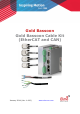
Gold Bassoon Gold Bassoon Cable Kit (EtherCAT and CAN) January 2014 (Ver. 1.000) www.elmomc.
Notice This guide is delivered subject to the following conditions and restrictions: • This guide contains proprietary information belonging to Elmo Motion Control Ltd. Such information is supplied solely for the purpose of assisting users of the Gold Bassoon servo drive in its installation. • The text and graphics included in this manual are for the purpose of illustration and reference only. The specifications on which they are based are subject to change without notice.
Table of Contents 3 MAN-G-BAS-CBLKIT (Ver. 1.000) Chapter 1: 1.1. Introduction .................................................................................................... 4 Cable Kit (CBL-GBASKIT) ................................................................................................. 4 Chapter 2: 24 VDC Auxiliary Supply................................................................................... 5 Chapter 3: Port A Cable .....................................................
Gold Bassoon Cable Kit (EtherCAT and CAN) 4 MAN-G-BAS-CBLKIT (Ver. 1.000) Chapter 1: I ntroduction This document provides the wiring details for the cables used to connect Elmo's Gold Bassoon servo drive with the end-user application. The servo drive-front pinouts are provided in the Gold Bassoon Digital Servo Drive Installation Guide. The cables come in one length: 2 meters (6 ½ feet). 1.1.
Gold Bassoon Cable Kit (EtherCAT and CAN) 5 MAN-G-BAS-CBLKIT (Ver. 1.000) Chapter 2: 24 VDC Aux iliary Supply The 24 VDC logic cable is a single twisted-pair 24-AWG double-shielded cable. It is connected using to the Gold Bassoon connector using an ending ferrule. The cable is open on the end side so that it can be connected to the power supply. The general pinout of the 24 VDC auxiliary supply is as follows: Pin No.
Gold Bassoon Cable Kit (EtherCAT and CAN) 6 MAN-G-BAS-CBLKIT (Ver. 1.000) Chapter 3: Port A Cable The Port A cable is a 6-pair 24-AWG shielded twisted-pair cable. It is connected using a D-type 15pin male connector to the Gold Bassoon Port A D-sub connector. The cable is open on the feedback side so that it can be connected to the motor-feedback connector. The general pinout of the Port A cable is as follows: Pin No.
Gold Bassoon Cable Kit (EtherCAT and CAN) 7 MAN-G-BAS-CBLKIT (Ver. 1.000) Pin No. Signal Color Twisted & Shielded Wire Plug Pin Positions 15-Pin D-Type Female Connector 15-Pin D-Type Male Connector Note: The specific functionality of each pin is described fully in of the Gold Bassoon Installation Guide. Figure 2: Feedback Port A Cable www.elmomc.
Gold Bassoon Cable Kit (EtherCAT and CAN) 8 MAN-G-BAS-CBLKIT (Ver. 1.000) Chapter 4: I / O Cable The I/O cable is an 8-pair 24-AWG double shielded twisted-pair cable. It is connected using a D-type 15-pin female connector to the Gold Bassoon on the servo drive side. The cable is open on the end side so that it can be connected to the controller interface connector. The general pinout of the I/O cable is as follows: Pin No.
Gold Bassoon Cable Kit (EtherCAT and CAN) MAN-G-BAS-CBLKIT (Ver. 1.000) 9 Pin Positions 15-Pin High Density D-Type Female Connector 15-Pin High Density D-Type Male Connector Note: The specific functionality of each pin is described fully in the Gold Bassoon Installation Guide. Figure 3: I/O Cable www.elmomc.
Gold Bassoon Cable Kit (EtherCAT and CAN) 10 MAN-G-BAS-CBLKIT (Ver. 1.000) Chapter 5: Port B Cable The Port B cable is a 4-pair 24-AWG shielded twisted-pair cable. It is connected using a D-type 9-pin male connector to the Gold Bassoon Port B D-sub connector. The cable is open on the feedback side so that it can be connected to the motor feedback connector. The general pinout of the Port B cable is as follows: Pin No.
Gold Bassoon Cable Kit (EtherCAT and CAN) 11 MAN-G-BAS-CBLKIT (Ver. 1.000) Pin No. Signal Color Twisted & Shielded Wire Plug Pin Positions 9-Pin D-Type Male Connector 9-Pin D-Type Female Connector Note: The specific functionality of each pin is described fully in the Gold Bassoon Installation Guide. Figure 4: Feedback Port B Cable www.elmomc.
Gold Bassoon Cable Kit (EtherCAT and CAN) 12 MAN-G-BAS-CBLKIT (Ver. 1.000) Chapter 6: Port C Cable The Port C cable is an 8-pair 24-AWG shielded twisted-pair cable. It is connected using a D-type 15-pin high density male connector to the Gold Bassoon Port C D-sub connector. The cable is open on the user interface side so that it can be connected to the controller interface connector. The general pinout of the Port C cable is as follows: Pin No.
Gold Bassoon Cable Kit (EtherCAT and CAN) 13 MAN-G-BAS-CBLKIT (Ver. 1.000) Pin Positions 15-Pin High Density D-Type Male Connector 15-Pin High Density D-Type Female Connector Note: The specific functionality of each pin is described fully in the Gold Bassoon Installation Guide. Figure 5: Feedback Port C Cable www.elmomc.
Gold Bassoon Cable Kit (EtherCAT and CAN) 14 MAN-G-BAS-CBLKIT (Ver. 1.000) Chapter 7: STO Cable The STO cable is a 24-AWG double-shielded twisted-pair cable. It is connected to the Gold Bassoon connector using an ending ferrule. The cable is open on the end-side so that it can be connected to the STO interface connector.
Gold Bassoon Cable Kit (EtherCAT and CAN) 15 MAN-G-BAS-CBLKIT (Ver. 1.000) Chapter 8: CAN Term inator The CAN terminator is used only for CAN applications. It is used to terminate the CAN communication line. The CAN terminations prevent the CAN signal reflection at the end of the physical lines. The reflection suppresses the CAN signal which may lead to Error Frames and causes the CAN controller message to be discarded.
Gold Bassoon Cable Kit (EtherCAT and CAN) MAN-G-BAS-CBLKIT (Ver. 1.000) 16 www.elmomc.