Gold Bassoon Digital Servo Drive Installation Guide EtherCAT and CAN July 2014 (Ver. 1.002) www.elmomc.
Notice This guide is delivered subject to the following conditions and restrictions: • This guide contains proprietary information belonging to Elmo Motion Control Ltd. Such information is supplied solely for the purpose of assisting users of the Gold Bassoon servo drive in its installation. • The text and graphics included in this manual are for the purpose of illustration and reference only. The specifications on which they are based are subject to change without notice.
Catalog Number and Configurations The Gold Bassoon is presented in three standard heat-sink configurations: Consult Elmo for a non- standard Heat-Sink configuration. Table of Contents |Warnings|www.elmomc.
Table of Contents MAN-G-BASIG-EC (Ver. 1.002) Chapter 1: This Installation Guide ..................................................................................... 6 Chapter 2: Safety Information .......................................................................................... 6 2.1 Warnings ........................................................................................................................ 7 2.2 Cautions ....................................................................
Table of Contents MAN-G-BASIG-EC (Ver. 1.002) 6.6 6.7 6.8 6.9 6.10 6.11 6.12 6.13 6.14 6.15 6.16 6.5.2 Hall Sensor ..................................................................................................... 33 6.5.3 Absolute Serial Type Encoder ........................................................................ 34 Port B ............................................................................................................................ 36 6.6.1 Incremental Encoder .............
Gold Bassoon Installation Guide MAN-G-BASIG-EC (Ver. 1.002) Chapter 1: 6 This I nstallation Guide This installation Guide details the technical data, pinouts, and power connectivity of the Gold Bassoon. For a comprehensive detailed description of the functions refer to the MAN-G-Panel Mounted Drives Hardware manual which describes Panel Mounted products.
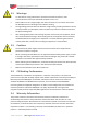
Gold Bassoon Installation Guide MAN-G-BASIG-EC (Ver. 1.002) 2.1 7 Warnings • To avoid electric arcing and hazards to personnel and electrical contacts, never connect/disconnect the servo drive while the power source is on. • Power cables can carry a high voltage, even when the motor is not in motion. Disconnect the Gold Bassoon from all voltage sources before servicing. • The high voltage products within the Gold Line range contain grounding conduits for electric current protection.
Gold Bassoon Installation Guide MAN-G-BASIG-EC (Ver. 1.002) Chapter 3: 8 Product Description The Gold Bassoon series of digital servo drives are highly resilient and designed to deliver the highest density of power and intelligence. The Gold Bassoon delivers up to 3.25 kW of continuous power in a compact package. The Gold Bassoon series are part of Elmo’s advanced Gold Line.
Gold Bassoon Installation Guide 9 MAN-G-BASIG-EC (Ver. 1.002) Chapter 4: 4.1 Technical I nform ation Physical Specifications Feature Units All Types Weight g (oz) L-Shaped Heat-Sink 0.65 Kg (22.90 oz) Fins Heat-Sink 1.10 Kg (36.70 oz) L-Shaped Heat-Sink 46.9 x 140x 105 (1.85" x 5.52" x 4.14") Fins Heat-Sink 71.4 x 140x 105 (2.82" x 5.52" x 4.14") Dimensions mm (in) Mounting method 4.
Gold Bassoon Installation Guide 10 MAN-G-BASIG-EC (Ver. 1.002) 4.3 Auxiliary Supply Feature Details Auxiliary power supply Isolated DC source only Auxiliary supply input voltage Without Fan: 18 to 30 VDC With Fan: 24VDC± 10% Auxiliary supply input power Without Fan: 6 With Fan: 16 4.4 Product Features Main Feature Details Presence and No.
Gold Bassoon Installation Guide 11 MAN-G-BASIG-EC (Ver. 1.002) Chapter 5: I nstallation The Gold Bassoon must be installed in a suitable environment and properly connected to its voltage supplies and the motor. 5.
Gold Bassoon Installation Guide MAN-G-BASIG-EC (Ver. 1.002) 5.2 Unpacking the Drive Components Before you begin working with the Gold Bassoon, verify that you have all of its components, as follows: • The Gold Bassoon servo drive • The Elmo Application Studio (EAS) software and software manual The Gold Bassoon is shipped in a cardboard box with Styrofoam protection. To unpack the Gold Bassoon: 1. Carefully remove the servo drive from the box and the Styrofoam. 2.
Gold Bassoon Installation Guide 13 MAN-G-BASIG-EC (Ver. 1.002) 5.3 Connectors Types The Gold Bassoon has the following connectors: Type Pins Function Port Front Connectors Front Connectors - EtherCAT Front Connectors - CAN RJ-45 8 Ethernet/EtherCAT IN communication RJ-45 8 EtherCAT OUT communication RJ-45 8 CAN communication RJ-45 8 CAN communication USB 4 USB communication USB port Socket D-Type 15 Feedback Port A Table of Contents |Connectors Types|www.elmomc.
Gold Bassoon Installation Guide 14 MAN-G-BASIG-EC (Ver. 1.
Gold Bassoon Installation Guide 15 MAN-G-BASIG-EC (Ver. 1.002) 5.3.1 Mating Connector Types Mating Pin Connector Function Manufacturing P/N (Pheonix) 2 Pin Fan MC 1,5/2-ST-3,81 6 Pin VL and STO MC 1,5/6-STF-3,5 4 Pin AC Input MSTBT 2,5/4-STF 5 Pin Motor Power MSTBT 2,5/5-STF Table of Contents |Connectors Types|www.elmomc.
Gold Bassoon Installation Guide MAN-G-BASIG-EC (Ver. 1.002) 5.4 Mounting the Gold Bassoon For optimum heat dissipation, the Gold Bassoon should be installed with the heat sink attached to the machine's chassis. It is recommended to mount the Gold Bassoon in the vertical position. M4 round head screws, one through each opening in the heat sink, are used to mount the Gold Bassoon (see the diagram below).
Gold Bassoon Installation Guide MAN-G-BASIG-EC (Ver. 1.002) 5.5 Connection Diagrams There is one connection diagram for EtherCAT and one for CAN in the Gold Bassoon models. 5.5.1 Connection Diagrams for EtherCAT Version The following describes the connection diagrams for the EtherCAT version. Figure 3: Gold Bassoon Connection Diagram for EtherCAT Table of Contents |Connection Diagrams|www.elmomc.
Gold Bassoon Installation Guide MAN-G-BASIG-EC (Ver. 1.002) 5.5.2 Connection Diagrams for CAN Version The following describes the connection diagrams for the CAN version. Figure 4: Gold Bassoon Connection Diagram for CAN Table of Contents |Connection Diagrams|www.elmomc.
Gold Bassoon Installation Guide 19 MAN-G-BASIG-EC (Ver. 1.002) Chapter 6: W iring Once the product is mounted, you are ready to wire the device. Proper wiring, grounding and shielding are essential for ensuring safe, immune and optimal servo performance of the drive. The following table legend describes the wiring symbols detailed in all installation guides. Wiring Symbol Description Earth connection (PE) Protective Earth Connection Common at the Controller Shielded cable with drain wire.
Gold Bassoon Installation Guide 20 MAN-G-BASIG-EC (Ver. 1.002) Wiring Symbol Description D-type Connector: The cable`s braid (Shield) must be connected to the D-sub shell (metal housing) Encoder Earthing. T The cable`s shield is connected to the chassis (PE) in the connector. Earthing the Encoder and connecting the Earth (PE) to the drive COMRET is mandatory to insure reliable operation, high noise immunity and rejection of voltage common mode interferences.
Gold Bassoon Installation Guide MAN-G-BASIG-EC (Ver. 1.002) 6.1 6.1.1 Basic Recommendations General 1. Use shielded cables. For best results, the cable should have an aluminum foil shield covered by copper braid, and should contain a drain wire. Use 24, 26 or 28 AWG twisted-pair shielded with drain wire cables. 2. Keep the cable as short as possible. Do not mount the power cables of the motor and power bus in the proximity of the control and feedback cables. 3.
Gold Bassoon Installation Guide MAN-G-BASIG-EC (Ver. 1.002) 6.1.2 Feedback Cable Port A and Port B Connector 1. On the motor side connections, ground the shield to the motor chassis. 2. At least One COMRET (Common Return) must be connected to the PE. Implement the following steps to connect the COMRET to the PE: a. At the drive, connect the feedback drain wire to one of the COMRET terminals in the D-Type feedback connector (Figure 6). b.
Gold Bassoon Installation Guide MAN-G-BASIG-EC (Ver. 1.002) 6.1.3 Feedback Cable Port C Connector 1. At the controller side connections, follow the controller manufacturer’s recommendations concerning the shield. 2. The connection of the Drain wire to the Port C is not mandatory. Figure 7: Feedback Port C Cable Assemblies 6.1.4 IO Cable Connector It is recommended to use shielded cable, but is not mandatory. Figure 8: Feedback IO Cable Assemblies Table of Contents |Basic Recommendations|www.
Gold Bassoon Installation Guide MAN-G-BASIG-EC (Ver. 1.002) 6.1.5 STO Cable Connector It is recommended to use shielded cable, but is not mandatory. Figure 9: STO Cable Assemblies Table of Contents |Basic Recommendations|www.elmomc.
Gold Bassoon Installation Guide 25 MAN-G-BASIG-EC (Ver. 1.002) 6.2 Motor Power Connector Pinouts See Chapter 8 in the in the MAN-G-Panel Mounted Drives Hardware manual for full details.
Gold Bassoon Installation Guide MAN-G-BASIG-EC (Ver. 1.002) Figure 10: Brushless Motor Power Connection Diagram Figure 11: DC Brushed Motor Power Connection Diagram 6.2.1 Motor Power To power the drive, connect the M1, M2, M3, and PE pins on the Gold Bassoon. The phase connection is arbitrary as Elmo Application Studio (EASII) will establish the proper commutation automatically during setup.
Gold Bassoon Installation Guide 27 MAN-G-BASIG-EC (Ver. 1.002) 6.3 Main Power The Gold Bassoon receives power from main power supplies and delivers power to the motor.
Gold Bassoon Installation Guide MAN-G-BASIG-EC (Ver. 1.002) 6.3.1 Direct-to-Mains Power Source (Non-Isolated) This section relates to the configuration of the drive, which is connected directly to the mains. To connect the non-isolated AC power supply: 1. For best noise immunity, a shielded (not twisted) cable is recommended (not mandatory) for the AC input cable. 2. A 4-wire shielded cable should be used: a.
Gold Bassoon Installation Guide MAN-G-BASIG-EC (Ver. 1.002) 6.3.1.2 Single-Phase Direct-to-Mains Connection Topology Figure 13: Non-Isolated Single-Phase Source - Connection Topology 6.3.2 Shunt Regulator A shunt regulator is included in the Gold Bassoon. The shunt regulator is a switching type, wherein the dissipative element (power resistor) is switched across the DC bus, whenever the voltage reaches a predetermined level.
Gold Bassoon Installation Guide 30 MAN-G-BASIG-EC (Ver. 1.002) 6.4 Auxiliary Power The Gold Bassoon always requires an external 24 VDC power supply, regardless of whether or not backup functionality is required. Pin Function Cable VL+ +24 V Auxiliary Supply Input Positive Auxiliary Power VL- 24 V RET Auxiliary Supply Input Return Auxiliary Power Pin Positions 2/6-Pin Pluggable 3.
Gold Bassoon Installation Guide MAN-G-BASIG-EC (Ver. 1.002) Figure 14: Auxiliary 24 VDC Power Supply Connection Diagram Table of Contents |Auxiliary Power|www.elmomc.
Gold Bassoon Installation Guide 32 MAN-G-BASIG-EC (Ver. 1.002) 6.5 Port A See Section 10.3 in the in the MAN-G-Panel Mounted Drives Hardware manual for full details.
Gold Bassoon Installation Guide MAN-G-BASIG-EC (Ver. 1.002) 6.5.1 Incremental Encoder The following figure describes the connections at Port A for the Incremental encoder. Figure 15: Port A D-Type Incremental Encoder Input – Recommended Connection Diagram 6.5.2 Hall Sensor The following figure describes the connections at Port A for the Hall Sensor. Figure 16: Hall Sensor Connection Diagram Table of Contents |Port A|www.elmomc.
Gold Bassoon Installation Guide MAN-G-BASIG-EC (Ver. 1.002) 6.5.3 Absolute Serial Type Encoder The following figures describe the connections at Port A for the Absolute Serial type encoders. Figure 17: Absolute Serial Encoder – Recommended D-Type Connection Diagram for EnDAT, Biss, and SSI Figure 18: Absolute Serial Encoder – Recommended D-Type Connection Diagram for Sensors Supporting Data Line Only (NRZ types, e.g., Panasonic / Mitutoyo / Sanyo Danki / Tamagawa) Table of Contents |Port A|www.elmomc.
Gold Bassoon Installation Guide MAN-G-BASIG-EC (Ver. 1.002) Figure 19: Absolute Serial Encoder – Recommended D-Type Connection Diagram for Stegmann Hiperface Table of Contents |Port A|www.elmomc.
Gold Bassoon Installation Guide 36 MAN-G-BASIG-EC (Ver. 1.002) 6.6 Port B See Section 10.4 in the in the MAN-G-Panel Mounted Drives Hardware manual for full details.
Gold Bassoon Installation Guide MAN-G-BASIG-EC (Ver. 1.002) 6.6.1 Incremental Encoder The following figure describes the connections at Port B for the Incremental encoder. Figure 20: Port B Incremental Encoder Input – Recommended D-Type Connection Diagram Table of Contents |Port B|www.elmomc.
Gold Bassoon Installation Guide MAN-G-BASIG-EC (Ver. 1.002) 6.6.2 Interpolated Analog Encoder The following figure describes the connections at Port B for the Interpolated Analog encoder. Figure 21: Port B - Interpolated Analog Encoder D-Type Connection Diagram Table of Contents |Port B|www.elmomc.
Gold Bassoon Installation Guide MAN-G-BASIG-EC (Ver. 1.002) 6.6.3 Resolver The following figure describes the connections at Port B for the Resolver encoder. Figure 22: Port B – Resolver D-Type Connection Diagram Table of Contents |Port B|www.elmomc.
Gold Bassoon Installation Guide 40 MAN-G-BASIG-EC (Ver. 1.002) 6.7 Port C and Analog Input The Port C connector includes the following functions: • Port C: Refer to Sections 10.5 in the in the MAN-G-Panel Mounted Drives Hardware manual for full details • Analog input: See Section 11.2 in the in the MAN-G-Panel Mounted Drives Hardware manual for full details.
Gold Bassoon Installation Guide 41 MAN-G-BASIG-EC (Ver. 1.002) Pin on Port C Signal Function Pin Positions 15-Socket High Density D-Type Connector Table 6: Port C Pin Assignments Table of Contents |Port C and Analog Input|www.elmomc.
Gold Bassoon Installation Guide MAN-G-BASIG-EC (Ver. 1.002) 6.7.1 Port C The following figure describes the connections at Port C for the Emulated Encoder Differential. Figure 23: Emulated Encoder Differential Output – Recommended D-Type Connection Diagram 6.7.2 Analog Input The following circuit describes the internal interface of the Analog input. Figure 24: Differential Analog D-Type Input Table of Contents |Port C and Analog Input|www.elmomc.
Gold Bassoon Installation Guide 43 MAN-G-BASIG-EC (Ver. 1.002) 6.8 STO See Chapter 9 in the in the MAN-G-Panel Mounted Drives Hardware manual for full details. Pin Function Cable STO1 STO1 Input STO cable STO2 STO2 Input STO cable STORET STO Return Signal STO cable STORET STO Return Signal STO cable Pin Positions 4/6-Pin Pluggable 3.5 mm Screw Flange Connector Table 7: STO Pin Assignments The following circuits describe the STO wiring options. 6.8.
Gold Bassoon Installation Guide MAN-G-BASIG-EC (Ver. 1.002) 6.8.2 TTL Mode TTL Voltage Level Figure 26: STO Input Connection – TTL Option 6.8.3 SINK Mode – PLC Voltage Level Refer to the diagrams below for the PLC Sink option connections which is not fully certified for STO. This option is not recommended for new designs. Figure 27: STO Input Connection – Sink Option Table of Contents |STO|www.elmomc.
Gold Bassoon Installation Guide MAN-G-BASIG-EC (Ver. 1.002) 6.8.4 STO Output There are two available options: • I/O and STO type without STO • I/O and STO type with STO If the STO STATUS OUT is configured, then OUT4 and IN6 will not be available. Refer to Figure 28 below for details of the connections. Refer to Chapter 9 in the in the MAN-G-Panel Mounted Drives Hardware manual for full details. Figure 28: STO Output Table of Contents |STO|www.elmomc.
Gold Bassoon Installation Guide MAN-G-BASIG-EC (Ver. 1.002) 6.9 Digital Inputs and Outputs Refer to Chapter 11 in the in the MAN-G-Panel Mounted Drives Hardware manual for full details.
Gold Bassoon Installation Guide MAN-G-BASIG-EC (Ver. 1.002) I/O Pins Signal 47 Function Pin Positions 15-Pin High Density D-Type Male Connector Table 8: I/O Connector Pin Assignments Table of Contents |Digital Inputs and Outputs|www.elmomc.
Gold Bassoon Installation Guide MAN-G-BASIG-EC (Ver. 1.002) 6.9.1 Digital Input and Output TTL Mode The following figure describes the connections at the I/O Port for the Digital Input and Output TTL Mode. Figure 29: Digital Input TTL Mode D-Type Connection Diagram Table of Contents |Digital Inputs and Outputs|www.elmomc.
Gold Bassoon Installation Guide MAN-G-BASIG-EC (Ver. 1.002) Figure 30: Digital Output D-Type Connection Diagram – TTL Option Table of Contents |Digital Inputs and Outputs|www.elmomc.
Gold Bassoon Installation Guide MAN-G-BASIG-EC (Ver. 1.002) 6.9.2 Digital Input and Output PLC Source Mode The following figure describes the connections at the I/O Port for the Digital Input and Output PLC Mode. Figure 31: Digital Input D-Type Connection Diagram – Source PLC Option Table of Contents |Digital Inputs and Outputs|www.elmomc.
Gold Bassoon Installation Guide MAN-G-BASIG-EC (Ver. 1.002) Figure 32: Digital Output D-Type Connection Diagram – Source PLC Option Table of Contents |Digital Inputs and Outputs|www.elmomc.
Gold Bassoon Installation Guide MAN-G-BASIG-EC (Ver. 1.002) 6.9.3 Digital Input and Output Sink Mode The following figure describes the connections at the I/O Port for the Digital Input and Output Sink Mode. Figure 33: Digital Input Sink Mode – PLC voltage level D-Type Connection Diagram Table of Contents |Digital Inputs and Outputs|www.elmomc.
Gold Bassoon Installation Guide MAN-G-BASIG-EC (Ver. 1.002) Figure 34: Digital Output as Sink Configuration D-Type Connection Diagram Table of Contents |Digital Inputs and Outputs|www.elmomc.
Gold Bassoon Installation Guide 54 MAN-G-BASIG-EC (Ver. 1.002) 6.10 Fan Connector (Optional) Notes: • Only available for G-BASXX/YYYXXXX1 • The Smart FAN algorithm starts working when the internal heat-sink temperature reaches 60°C. • The optional Fan may be required when the drive is used in tough environmental conditions leading to extreme temperatures causing the drive to exceed its thermal limits.
Gold Bassoon Installation Guide 55 MAN-G-BASIG-EC (Ver. 1.002) 6.11 USB 2.0 See Section 12.1 in the in the MAN-G-Panel Mounted Drives Hardware manual for full details. Pin on USB Signal Function 1 USB VBUS USB VBUS 5V Detector 2 USBD- USB _N line 3 USBD+ USB _P line 5 USB COMRET USB communication return Pin Positions USB Device Mini B Plug USB Mini B Connecter Table 10: USB 2.0 Pin Assignments Figure 35: USB Network Diagram Table of Contents |USB 2.0|www.elmomc.
Gold Bassoon Installation Guide MAN-G-BASIG-EC (Ver. 1.002) 6.12 Drive Status Indicator The Gold Bassoon is equipped with several light-emitting diode (LED) indicators. The red/green dual LED is used for immediate indication of the following states: • Initiation state: In this state the LED indicates whether the drive is in the boot state (blinking red) or in the operational state (steady red).
Gold Bassoon Installation Guide 57 MAN-G-BASIG-EC (Ver. 1.002) 6.13 EtherCAT Communications Version Fieldbus communications are industrial network protocols for real-time distributed control that allows connection of servo drives. The Gold Bassoon supports the following EtherCAT fieldbus type industrial network protocol: Fieldbus Type Product Number EtherCAT + Switches G-BASXX/YYYFXXXX 6.13.1 EtherCAT IN/Ethernet Pinouts Refer to section 12.
Gold Bassoon Installation Guide 58 MAN-G-BASIG-EC (Ver. 1.002) 6.13.2 EtherCAT OUT Pinouts See Section 12.2 in the MAN-G-Panel Mounted Drives Hardware manual for the electrical diagram.
Gold Bassoon Installation Guide MAN-G-BASIG-EC (Ver. 1.002) 6.13.3 EtherCAT Wiring Figure 35 describes the wiring diagram for the EtherCAT connections. Figure 36: EtherCAT RJ-45 Connections 6.13.4 EtherCAT Link Indicators The Gold Bassoon can serve as an EtherCAT slave device. For this purpose it has two RJ-45 connectors, which are designated as EtherCAT In and EtherCAT Out. Each of these RJ-45 connectors has two status LEDs, which are shown in Figure 36.
Gold Bassoon Installation Guide MAN-G-BASIG-EC (Ver. 1.002) 6.13.5 EtherCAT Status Indicator The EtherCAT status indicator is a red/green dual LED. It combines run indication (when it is green) and error indication (when it is red) of the EtherCAT device. 6.13.6 EtherCAT Switches Note: This option is only available in the G-BASXX/YYYFXXXX type. The EtherCAT address of each axis is specified by the two EtherCAT switches. For full details, see Section 6.8.2.4 in the MAN-GDrive Hardware manual.
Gold Bassoon Installation Guide 61 MAN-G-BASIG-EC (Ver. 1.002) 6.14 CAN Communications Version Fieldbus communications are industrial network protocols for real-time distributed control that allows connection of servo drives. The Gold Bassoon supports the following CAN fieldbus type industrial network protocol. Fieldbus Type Product Number CAN G-BASXX/YYYSXXXX See Section 12.4 in the MAN-G-Panel Mounted Drives Hardware manual for the electrical diagram.
Gold Bassoon Installation Guide 62 MAN-G-BASIG-EC (Ver. 1.002) 6.14.1 CAN Wiring Figure 37 describes the CAN wiring diagram below. Caution When installing the CAN communications, ensure that each servo drive is allocated a unique ID. Otherwise, the CAN network may hang. Figure 38: Gold Bassoon Connection Diagram – CAN Table of Contents |CAN Communications Version|www.elmomc.
Gold Bassoon Installation Guide MAN-G-BASIG-EC (Ver. 1.002) 6.15 63 Powering Up After the Gold Bassoon is connected to its device, it is ready to be powered up. Caution: Before applying power, ensure that the DC supply is within the specified range and that the proper plus-minus connections are in order. 6.16 Initializing the System After the Gold Bassoon has been connected and mounted, the system must be set up and initialized.
Gold Bassoon Installation Guide MAN-G-BASIG-EC (Ver. 1.002) Chapter 7: Gold Bassoon Dim ensions This chapter provides detailed technical dimensions regarding the Gold Bassoon. Figure 39: Gold Bassoon with Standard L-shaped Heat-Sink Table of Contents |Initializing the System|www.elmomc.
Gold Bassoon Installation Guide MAN-G-BASIG-EC (Ver. 1.002) Figure 40: Gold Bassoon with Fins Heat-Sink and Fan Table of Contents |Initializing the System|www.elmomc.
Table of Contents ||www.elmomc.