Gold DC Whistle Gold DC Whistle Cable Kit (EtherCAT and CAN) January 2014 (Ver. 1.100) www.elmomc.
Notice This guide is delivered subject to the following conditions and restrictions: • This guide contains proprietary information belonging to Elmo Motion Control Ltd. Such information is supplied solely for the purpose of assisting users of the Gold DC Whistle servo drive in its installation. • The text and graphics included in this manual are for the purpose of illustration and reference only. The specifications on which they are based are subject to change without notice.
Table of Contents MAN-G-DCWHI-CBLKIT (Ver. 1.100) Chapter 1: 1.1. Introduction .................................................................................................... 4 Cable Kit.......................................................................................................................... 4 Chapter 2: Feedback Port A Cable (CBL-GPORTA-B2) ........................................................ 5 Chapter 3: Feedback Port B Cable (CBL-GPORTB-B2) ................................
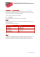
Gold DC Whistle Cable Kit (EtherCAT and CAN) 4 MAN-G-DCWHI-CBLKIT (Ver. 1.100) Chapter 1: I ntroduction This document provides the wiring details for the cables used to connect Elmo's Gold DC Whistle servo drive with the end-user application. The servo drive-side pinouts are provided in the Gold DC Whistle Digital Servo Drive Installation Guide. The cables come in one length: 2 meters (6 ½ feet). 1.1. Cable Kit The catalog number of the Gold Cello cable kit is CBL- GDCWHIKIT02.
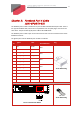
Gold DC Whistle Cable Kit (EtherCAT and CAN) 5 MAN-G-DCWHI-CBLKIT (Ver. 1.100) Chapter 2: Feedback Port A Cable (CBL-GP OR TA-B2) The feedback port A cable is made from a 6-pair 24-AWG shielded twisted-pair cable. There is one type of feedback cable, which uses a 12-pin Molex 2.54 mm pitch plug to connect to the servo drive. The part number (P/N) of this cable is CBL-GPORTA-B2. The feedback port A cable is open on the motor side so that it can be connected to the motorfeedback connector.
Gold DC Whistle Cable Kit (EtherCAT and CAN) 6 MAN-G-DCWHI-CBLKIT (Ver. 1.100) Note: The specific functionality of each pin is described fully in the Gold DC Whistle Digital Servo Drive Installation Guide. Figure 1: Single-Sided Main Feedback Cable (Part No. CBL-GPORTA-B2) www.elmomc.
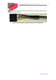
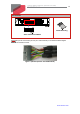
Gold DC Whistle Cable Kit (EtherCAT and CAN) 7 MAN-G-DCWHI-CBLKIT (Ver. 1.100) Chapter 3: Feedback Port B Cable (CBL-GP OR TB-B2) The feedback port B cable is a 4-pair 24-AWG shielded twisted-pair cable. It is connected using an 8-pin Molex 2.54 mm pitch plug. The part number (P/N) of this cable is CBL-GPORTB-B2. The cable is open on the motor side so that it can be connected to the motor feedback connector. The general pinout of the feedback port B cable is as follows: Pin No.
Gold DC Whistle Cable Kit (EtherCAT and CAN) 8 MAN-G-DCWHI-CBLKIT (Ver. 1.100) Note: The specific functionality of each pin is described fully in the Gold DC Whistle Digital Servo Drive Installation Guide. Figure 2: Feedback Port B Cable (Part No. CBL-GPORTB-B2) www.elmomc.
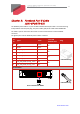
Gold DC Whistle Cable Kit (EtherCAT and CAN) 9 MAN-G-DCWHI-CBLKIT (Ver. 1.100) Chapter 4: Port C & I / O Cable (CBL-GP OR TCI O-B2) The Port C & IO cable is a 12-pair 24-AWG shielded twisted-pair cable. It is connected using a 24-pin Molex 2.54 mm pitch plug. The part number (P/N) of this cable is CBL-GPORTCIO-B2. The cable is open on the motor side so that it can be connected to the controller interface connector.
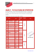
Gold DC Whistle Cable Kit (EtherCAT and CAN) 10 MAN-G-DCWHI-CBLKIT (Ver. 1.100) Pin Positions 24-Pin Molex Plug 24-Pin 2.54 mm Pitch Molex Note: The specific functionality of each pin is described fully in the Gold DC Whistle Digital Servo Drive Installation Guide. Figure 3: I/O Cable (Part No. CBL-GPORTCIO-B2) www.elmomc.
Gold DC Whistle Cable Kit (EtherCAT and CAN) 11 MAN-G-DCWHI-CBLKIT (Ver. 1.100) Chapter 5: STO Cable (CBL-GSTOCOM -B2) The STO cable is a 26-AWG shielded twisted-pair cable. It is connected using a 3-pin Molex 2.54 mm pitch plug. The part number (P/N) of this cable is CBL-GSTOCOM-B2. The cable is open on the motor side so that it can be connected to the STO interface connector. The general pinout of the STO cable is as follows: Pin No.
Gold DC Whistle Cable Kit (EtherCAT and CAN) 12 MAN-G-DCWHI-CBLKIT (Ver. 1.100) Chapter 6: CAN Term inator (ACC-TR M -01) W hen requested specifically The CAN terminations prevent the CAN signal reflection at the end of the physical lines. The reflection suppresses the CAN signal (the CAN signal leads to Error Frames and causes the CAN controller message to be discarded). 120 Ohm resistors are required on both physical ends of the CAN network to prevent the signal reflection.
Gold DC Whistle Cable Kit (EtherCAT and CAN) MAN-G-DCWHI-CBLKIT (Ver. 1.100) 13 www.elmomc.