Gold DC Whistle Digital Servo Drive Installation Guide EtherCAT and CAN June 2014 (Ver. 1.700) www.elmomc.
Notice This guide is delivered subject to the following conditions and restrictions: • This guide contains proprietary information belonging to Elmo Motion Control Ltd. Such information is supplied solely for the purpose of assisting users of the Gold DC Whistle servo drive in its installation. • The text and graphics included in this manual are for the purpose of illustration and reference only. The specifications on which they are based are subject to change without notice.
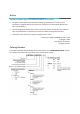
Cable Kit Catalog number: CBL-GDCWHIKIT02 (can be ordered separately). For further details, see the documentation for this cable kit (MAN-G-DCWHI-CBLKIT.pdf). Revision History Version Date Details Ver. 1.
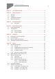
Table of Contents MAN-G-DCWHIIG-EC (Ver. 1.700) Chapter 1: This Installation Guide .................................................................................6 Chapter 2: Safety Information ......................................................................................6 2.1. 2.2. 2.3. 2.4. Warnings .................................................................................................................... 7 Cautions .................................................................
Table of Contents MAN-G-DCWHIIG-EC (Ver. 1.700) 6.6. 6.7. 6.8. 6.9. 6.10. 6.11. 6.12. 6.13. Port A (J1) .................................................................................................................35 6.6.1. Incremental Encoder .................................................................................36 6.6.2. Halls Sensor ...............................................................................................36 6.6.3. Absolute Serial Encoder...........................
Gold DC Whistle Installation Guide MAN-G-DCWHIIG-EC (Ver. 1.700) 6 Chapter 1: This I nstallation Guide This installation Guide details the technical data, pinouts, wiring and power connectivity of the Gold DC Whistle. For a comprehensive detailed description of the functions refer to the MAN-G-Panel Mounted Drives Hardware manual which describes Panel Mounted products.
Gold DC Whistle Installation Guide MAN-G-DCWHIIG-EC (Ver. 1.700) 2.1. 7 Warnings • To avoid electric arcing and hazards to personnel and electrical contacts, never connect/disconnect the servo drive while the power source is on. • Power cables can carry a high voltage, even when the motor is not in motion. Disconnect the Gold DC Whistle from all voltage sources before servicing. • The high voltage products within the Gold Line range contain grounding conduits for electric current protection.
Gold DC Whistle Installation Guide MAN-G-DCWHIIG-EC (Ver. 1.700) 8 Chapter 3: Product Description The Gold DC Whistle is an advanced high power density servo drive which delivers up to 1.6 kW of continuous power or 3.2 kW of peak power in a 222.5 cc (13.58 in³) package (115 x 75 x 25.8 mm or 4.5" x 3.0" x 1"). This advanced, high power density servo drive provides top performance, advanced networking and built-in safety, as well as a fully featured motion controller and local intelligence.
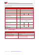
Gold DC Whistle Installation Guide 9 MAN-G-DCWHIIG-EC (Ver. 1.700) Chapter 4: Technical I nform ation 4.1. Physical Specifications Feature Units Weight Dimensions All Types g (oz) 267 g (9.42 oz) mm (in) 115 x 75 x 25.8 mm (4.5" x 3.0" x 1") Mounting method 4.2. Wall Mount / Book Shelf Technical Data Feature Units 1/100 2.
Gold DC Whistle Installation Guide 10 MAN-G-DCWHIIG-EC (Ver. 1.
Gold DC Whistle Installation Guide 11 MAN-G-DCWHIIG-EC (Ver. 1.700) 4.2.2. Product Features Main Feature Details Presence and No.
Gold DC Whistle Installation Guide MAN-G-DCWHIIG-EC (Ver. 1.700) 12 Chapter 5: I nstallation The Gold DC Whistle must be installed in a suitable environment and properly connected to its voltage supplies and the motor. 5.1.
Gold DC Whistle Installation Guide 13 MAN-G-DCWHIIG-EC (Ver. 1.700) 5.2. Connector Types The Gold DC Whistle has ten connectors. No. Pins Type Function Bottom Connectors 4 Phoenix 5 mm Pitch ‘HC’ Motor phases 3 Phoenix 5 mm Pitch ‘HC’ Main Power 2 Phoenix 3.81 mm Pitch ‘HC’ Auxiliary supply input Front Connectors Front Connectors - EtherCAT Table of Contents ||Connector Types|www.elmomc.
Gold DC Whistle Installation Guide 14 MAN-G-DCWHIIG-EC (Ver. 1.700) No. Pins Type Function Front Connectors - CAN 3 2.54 mm Pitch Molex STO 24 2.54 mm Pitch Molex Feedback port C and I/O 8 2.54 mm Pitch Molex Feedback port B 12 2.54 mm Pitch Molex Feedback port A Top Connectors Top Connectors - EtherCAT Table of Contents ||Connector Types|www.elmomc.
Gold DC Whistle Installation Guide 15 MAN-G-DCWHIIG-EC (Ver. 1.700) No. Pins Type Function Top Connectors - CAN 5 USB Device Mini-B USB EtherCAT Version 8 RJ-45 EtherCAT in 8 RJ-45 EtherCAT out CAN Version 8 RJ-45 CAN 8 RJ-45 CAN Table 2: Connector Types The pinouts in Chapter 6: Wiring describe the function of each pin in the Gold DC Whistle connectors that are listed in Table 2. Table of Contents ||Connector Types|www.elmomc.
Gold DC Whistle Installation Guide MAN-G-DCWHIIG-EC (Ver. 1.700) 5.3. 16 Mounting the Gold DC Whistle The Gold DC Whistle has been designed for two standard mounting options: • Wall Mount along the back (can also be mounted horizontally on a metal surface) • Book Shelf along the side M4 round head screws, one through each opening in the heat sink, are used to mount the Gold DC Whistle (see the diagram below).
Gold DC Whistle Installation Guide MAN-G-DCWHIIG-EC (Ver. 1.700) 5.4. The Gold DC Whistle Connection Diagram Figure 2: The Gold DC Whistle Connection Diagram – EtherCAT Table of Contents ||The Gold DC Whistle Connection Diagram|www.elmomc.
Gold DC Whistle Installation Guide MAN-G-DCWHIIG-EC (Ver. 1.700) Figure 3: The Gold DC Whistle Connection Diagram - CAN Table of Contents ||The Gold DC Whistle Connection Diagram|www.elmomc.
Gold DC Whistle Installation Guide 19 MAN-G-DCWHIIG-EC (Ver. 1.700) Chapter 6: W iring Once the product is mounted, you are ready to wire the device. Proper wiring, grounding and shielding are essential for ensuring safe, immune and optimal servo performance of the drive. The following table legend describes the wiring symbols detailed in all installation guides. Wiring Symbol Description Earth connection (PE) Protective Earth Connection Common at the Controller Shielded cable with drain wire.
Gold DC Whistle Installation Guide MAN-G-DCWHIIG-EC (Ver. 1.700) 6.1. 6.1.1. 20 Basic Recommendations General 1. Use shielded cables. For best results, the cable should have an aluminum foil shield covered by copper braid, and should contain a drain wire. Use 24, 26 or 28 AWG twisted-pair shielded with drain wire cables. 2. Keep the cable as short as possible. Do not mount the power cables of the motor and power bus in the proximity of the control and feedback cables. 3.
Gold DC Whistle Installation Guide MAN-G-DCWHIIG-EC (Ver. 1.700) 6.1.2. 21 Feedback Cable Port A and Port B Connector 1. On the motor side connections, ground the shield to the motor chassis. 2. At least One COMRET (Common Return) must be connected to the PE. Implement the following steps to connect the COMRET to the PE: a. At the drive, connect the feedback drain wire to one of the COMRET terminals in the Molex feedback connector (Figure 5. b.
Gold DC Whistle Installation Guide MAN-G-DCWHIIG-EC (Ver. 1.700) 6.1.3. 22 Feedback Cable Port C Connector 1. At the controller side connections, follow the controller manufacturer’s recommendations concerning the shield. 2. The connection of the Drain wire to the Port C is not mandatory. Figure 7: Feedback Port C Cable Assemblies 6.1.4. IO Cable Connector It is recommended to use shielded cable, but is not mandatory.
Gold DC Whistle Installation Guide MAN-G-DCWHIIG-EC (Ver. 1.700) 6.1.5. STO (Port C) Cable Connector It is recommended to use shielded cable, but is not mandatory. Figure 9: STO Cable Assemblies Table of Contents ||Basic Recommendations|www.elmomc.
Gold DC Whistle Installation Guide 24 MAN-G-DCWHIIG-EC (Ver. 1.700) 6.2. Motor Power Connector Pinouts (J14) See Chapter 8 in the in the MAN-G-Panel Mounted Drives Hardware manual for full details.
Gold DC Whistle Installation Guide MAN-G-DCWHIIG-EC (Ver. 1.700) Figure 11: Brushed Motor Power Connection Diagram Table of Contents ||Motor Power Connector Pinouts (J14)|www.elmomc.
Gold DC Whistle Installation Guide MAN-G-DCWHIIG-EC (Ver. 1.700) 6.3. 26 Main and Auxiliary Power The Gold DC Whistle receives power from main and auxiliary supplies and delivers power to the motor. 6.3.1. Description This section describes the Main and Auxiliary Power for power ratings 200V and 100V, and provides details for the optional Backup (Auxiliary) Supply.
Gold DC Whistle Installation Guide 27 MAN-G-DCWHIIG-EC (Ver. 1.700) 6.3.2. Main Power (J13) Pin (J13) Signal Function Cable 1 VP+ Positive Power input DC Power 2 PR Power return DC Power 3 PE Protective Earth DC Power 3-Pin Phoenix Plug-in Connector 3-Pin Phoenix 5 mm Pitch ‘HC’ Table 4: Connectors for Main Power Connect the DC power cable to the VP+ and PR terminals on the Main Power Connector. To connect the DC power supply: 1.
Gold DC Whistle Installation Guide 28 MAN-G-DCWHIIG-EC (Ver. 1.700) 6.3.3. Auxiliary Power Supply (J12) Pin (J12) Signal Function Cable 1 VL+ Auxiliary Supply Input DC Power 2 PR Auxiliary Supply Return DC Power 2-Pin Phoenix Plug-in Connector 2-Pin Phoenix 3.81 mm Pitch Table 5: Aux. Power Connector – Pin Assignments Caution: Power from the Gold DC Whistle to the motor must come from the Main Supply and not from the Auxiliary Supply.
Gold DC Whistle Installation Guide MAN-G-DCWHIIG-EC (Ver. 1.700) 6.3.3.1. 29 Power Rating 200 V For Power Rating 200 V, two power isolated DC power sources are required, main power 12 - 195V and auxiliary Power 12-95V for the logic. Figure 12: 200 VDC Power Source Connection Diagram Table of Contents ||Main and Auxiliary Power|www.elmomc.
Gold DC Whistle Installation Guide MAN-G-DCWHIIG-EC (Ver. 1.700) 6.3.3.2. Power Rating 100 V 6.3.3.2.a Single Power Supply 30 For power rating 100 V , a single Power Supply is required which contains a “smart” control-supply algorithm, enabling the Gold DC Whistle to operate with only one power supply with no need for an auxiliary power supply for the logic. Figure 13: Main Power Supply Connection Diagram (no Auxiliary Supply) 6.3.3.2.
Gold DC Whistle Installation Guide MAN-G-DCWHIIG-EC (Ver. 1.700) 6.4. Drive Status Indicator Figure 15 shows the position of the red/green dual LED, which is used for immediate indication of the Initiation and Working states. For details refer to Chapter 7 Drive Status Indicator, in the MAN-G-Panel Mounted Drives Hardware manual.
Gold DC Whistle Installation Guide 32 MAN-G-DCWHIIG-EC (Ver. 1.700) 6.5. STO (Safe Torque Off) (J11) See Chapter 9 in the in the MAN-G-Panel Mounted Drives Hardware manual for full details. Pin (J11) Signal Function 1 STO1 STO1 input (default 24 V) 2 STO2 STO2 input (default 24 V) 3 STO_RET STO signal return 3-Pin Molex Plug This cable is included in the cable kit described in Section 3.1.1. 3-Pin 2.
Gold DC Whistle Installation Guide MAN-G-DCWHIIG-EC (Ver. 1.700) 6.5.1. Source Mode – PLC Voltage Level Refer to the diagrams below for the PLC Source option connection. Figure 17: STO Molex Type Input Connection – PLC Source Option 6.5.2. TTL Mode – TTL Voltage Level Refer to the diagrams below for TTL option connection. Figure 18: STO Input Connection – TTL Option Table of Contents ||STO (Safe Torque Off) (J11)|www.elmomc.
Gold DC Whistle Installation Guide MAN-G-DCWHIIG-EC (Ver. 1.700) 6.5.3. 34 Sink Mode – PLC Voltage Level Refer to the diagrams below for the PLC Sink option connections which is not fully certified for STO. This option is not recommended for new designs. Figure 19: STO Input Connection – Sink Option Table of Contents ||STO (Safe Torque Off) (J11)|www.elmomc.
Gold DC Whistle Installation Guide 35 MAN-G-DCWHIIG-EC (Ver. 1.700) 6.6. Port A (J1) See Section 10.3 in the in the MAN-G-Panel Mounted Drives Hardware manual for full details.
Gold DC Whistle Installation Guide MAN-G-DCWHIIG-EC (Ver. 1.700) 6.6.1. 36 Incremental Encoder Figure 20: Port A Molex Type Incremental Encoder Input – Recommended Connection Diagram 6.6.2. Halls Sensor Figure 21: Molex Type Hall Sensors Connection Diagram Table of Contents ||Port A (J1)|www.elmomc.
Gold DC Whistle Installation Guide MAN-G-DCWHIIG-EC (Ver. 1.700) 6.6.3. 37 Absolute Serial Encoder The following figures describe the connections at Port A for the Absolute Serial type encoders. Figure 22: Absolute Serial Encoder – Recommended Connection Diagram for EnDAT, Biss, SSI Figure 23: Absolute Serial Encoder – Recommended Connection Diagram for Sensors Supporting Data Line Only (NRZ types, e.g., Panasonic / Mitutoyo / Sanyo Danki / Tamagawa) Table of Contents ||Port A (J1)|www.elmomc.
Gold DC Whistle Installation Guide MAN-G-DCWHIIG-EC (Ver. 1.700) 6.6.3.1. Hiperface The following figure describes the connection diagram. Figure 24: Absolute Serial Encoder – Recommended Molex Type Connection Diagram for Stegmann Hiperface Table of Contents ||Port A (J1)|www.elmomc.
Gold DC Whistle Installation Guide 39 MAN-G-DCWHIIG-EC (Ver. 1.700) 6.7. Port B (J3) See Section 10.4 in the in the MAN-G-Panel Mounted Drives Hardware manual for full details.
Gold DC Whistle Installation Guide MAN-G-DCWHIIG-EC (Ver. 1.700) 6.7.1. Incremental Encoder The following figure describes the connections at Port B for the Incremental encoder. Figure 25: Port B Incremental Encoder Input – Recommended Connection Diagram Table of Contents ||Port B (J3)|www.elmomc.
Gold DC Whistle Installation Guide MAN-G-DCWHIIG-EC (Ver. 1.700) 6.7.2. Interpolated Analog Encoder The following figure describes the connections at Port B for the Interpolated Analog encoder. Figure 26: Port B - Interpolated Analog Encoder Molex Type Connection Diagram Table of Contents ||Port B (J3)|www.elmomc.
Gold DC Whistle Installation Guide MAN-G-DCWHIIG-EC (Ver. 1.700) 6.7.3. Resolver Figure 27: Port B – Resolver Molex Type Connection Diagram Table of Contents ||Port B (J3)|www.elmomc.
Gold DC Whistle Installation Guide 43 MAN-G-DCWHIIG-EC (Ver. 1.700) 6.8. Port C, Digital I/Os, and Analog Inputs (J2) The Port C connector includes the following functions: • Port C: Refer to Sections 10.5 in the in the MAN-G-Panel Mounted Drives Hardware manual for full details • I/O: Refer to Chapter 11 in the in the MAN-G-Panel Mounted Drives Hardware manual for full details. • Analog input: See Section 11.2 in the in the MAN-G-Panel Mounted Drives Hardware manual for full details.
Gold DC Whistle Installation Guide 44 MAN-G-DCWHIIG-EC (Ver. 1.700) Pin Positions Cable Connector 24-Pin Molex Plug This cable is included in the cable kit described in Section 3.1.1. 24-Pin 2.54 mm Pitch Molex Table 9: Port C Feedback Out and I/O Table of Contents ||Port C, Digital I/Os, and Analog Inputs (J2)|www.elmomc.
Gold DC Whistle Installation Guide MAN-G-DCWHIIG-EC (Ver. 1.700) 6.8.1. 45 Port C – Emulated Encoder Output The following figure describes the connections at Port C for the Emulated Encoder Differential. Figure 28: Emulated Encoder Differential Output – Recommended Connection Diagram Note that the user is required to connect a 120 Ω termination at the end of each differential line. Table of Contents ||Port C, Digital I/Os, and Analog Inputs (J2)|www.elmomc.
Gold DC Whistle Installation Guide MAN-G-DCWHIIG-EC (Ver. 1.700) 6.8.2. Analog Input The following circuit describes the internal interface of the Analog input. Figure 29: Differential Analog Input Table of Contents ||Port C, Digital I/Os, and Analog Inputs (J2)|www.elmomc.
Gold DC Whistle Installation Guide MAN-G-DCWHIIG-EC (Ver. 1.700) 6.8.3. 47 Digital Input and Output TTL Mode The following figure describes the connections at the I/O Port for the Digital Input and Output TTL Mode. Figure 30: Digital Input TTL Mode Connection Diagram Table of Contents ||Port C, Digital I/Os, and Analog Inputs (J2)|www.elmomc.
Gold DC Whistle Installation Guide MAN-G-DCWHIIG-EC (Ver. 1.700) Figure 31: Digital Output Connection Diagram – TTL Option Table of Contents ||Port C, Digital I/Os, and Analog Inputs (J2)|www.elmomc.
Gold DC Whistle Installation Guide MAN-G-DCWHIIG-EC (Ver. 1.700) 6.8.4. 49 Digital Input and Output PLC Source Mode The following figure describes the connections at the I/O Port for the Digital Input and Output PLC Mode. Figure 32: Digital Input Connection Diagram – Source PLC Option Table of Contents ||Port C, Digital I/Os, and Analog Inputs (J2)|www.elmomc.
Gold DC Whistle Installation Guide MAN-G-DCWHIIG-EC (Ver. 1.700) Figure 33: Digital Output Connection Diagram – Source PLC Option Table of Contents ||Port C, Digital I/Os, and Analog Inputs (J2)|www.elmomc.
Gold DC Whistle Installation Guide MAN-G-DCWHIIG-EC (Ver. 1.700) 6.8.5. 51 Digital Input and Output Sink Mode The following figure describes the connections at the I/O Port for the Digital Input and Output Sink Mode. Figure 34: Digital Input Sink Mode – PLC voltage level Molex Type Connection Diagram Table of Contents ||Port C, Digital I/Os, and Analog Inputs (J2)|www.elmomc.
Gold DC Whistle Installation Guide MAN-G-DCWHIIG-EC (Ver. 1.700) Figure 35: Digital Output as Sink Configuration Molex Type Connection Diagram Table of Contents ||Port C, Digital I/Os, and Analog Inputs (J2)|www.elmomc.
Gold DC Whistle Installation Guide 53 MAN-G-DCWHIIG-EC (Ver. 1.700) 6.9. USB 2.0 (J9) See Section 12.1 in the in the MAN-G-Panel Mounted Drives Hardware manual for full details. Pin (J9) Signal Function 1 USB VBUS USB VBUS 5 V 2 USBD- USB _N line 3 USBD+ USB _P line 5 USB COMRET USB communication return Pin Positions Cable Connector USB Device Mini-B Plug USB Device Mini-B Table 10: USB 2.0 Pin Assignments Figure 36: USB Network Diagram Table of Contents ||USB 2.0 (J9)|www.elmomc.
Gold DC Whistle Installation Guide 54 MAN-G-DCWHIIG-EC (Ver. 1.700) 6.10. EtherCAT Communication Version Fieldbus communications are industrial network protocols for real-time distributed control that allows connection of servo drives. The Gold DC Whistle supports the following EtherCAT fieldbus type industrial network protocol: Fieldbus Type Product Number EtherCAT G-DCWHI XX/YYYEXX 6.10.1. EtherCAT IN/Ethernet Pin Assignments (J7) Refer to section 12.
Gold DC Whistle Installation Guide 55 MAN-G-DCWHIIG-EC (Ver. 1.700) 6.10.2. EtherCAT OUT Pin Assignments (J8) See Section 12.2 in the MAN-G-Panel Mounted Drives Hardware manual for the electrical diagram. Pin (J8) Signal Function 1 EtherCAT_OUT_TX+ EtherCAT out transmit + 2 EtherCAT_OUT_TX- EtherCAT out transmit - 3 EtherCAT_OUT_RX+ EtherCAT out receive + 4, 5 6 7, 8 N/A EtherCAT_OUT_RX- EtherCAT out receive - N/A Connectors Standard Ethernet CAT5 Cable 8-Pin RJ-45 6.10.3.
Gold DC Whistle Installation Guide MAN-G-DCWHIIG-EC (Ver. 1.700) 6.10.4. 56 EtherCAT Status Indicator Figure 38: EtherCAT Status LED The EtherCAT status indicator is a single red/green dual bi-colored LED that combines the green RUN indicator and the red ERROR indicator of the EtherCAT state machine. For further details, see the EtherCAT Application Manual. Note: There is no Gold DC Whistle ECAT Status indicator equivalent in the CAN version, refer to the figure below.
Gold DC Whistle Installation Guide 57 MAN-G-DCWHIIG-EC (Ver. 1.700) 6.11. CAN Communication Version Fieldbus communications are industrial network protocols for real-time distributed control that allows connection of servo drives. The Gold DC Whistle supports the following CAN fieldbus type industrial network protocol: Fieldbus Type Product Number CAN G-DCWHI XX/YYYSXX See Section 12.4 in the MAN-G-Panel Mounted Drives Hardware manual for the electrical diagram.
Gold DC Whistle Installation Guide 58 MAN-G-DCWHIIG-EC (Ver. 1.700) 6.11.1. CAN Wiring Caution When installing the CAN communications, ensure that each servo drive is allocated a unique ID. Otherwise, the CAN network may hang. Figure 40: Gold DC Whistle Connection Diagram – CAN Table of Contents ||CAN Communication Version|www.elmomc.
Gold DC Whistle Installation Guide MAN-G-DCWHIIG-EC (Ver. 1.700) 59 6.12. Powering Up After the Gold DC Whistle is connected to its device, it is ready to be powered up. Caution: Before applying power, ensure that the DC supply is within the specified range and that the proper plus-minus connections are in order. 6.13. Initializing the System After the Gold DC Whistle has been connected and mounted, the system must be set up and initialized.
Gold DC Whistle Installation Guide MAN-G-DCWHIIG-EC (Ver. 1.700) Chapter 7: Dim ensions This chapter provides detailed technical information regarding the Gold DC Whistle. Table of Contents ||www.elmomc.
Table of Contents ||www.elmomc.