
Manual
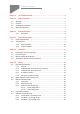
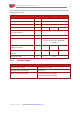

Table of Contents
MAN-G-DCWHIIG-EC (Ver. 1.700)
4
Chapter 1: This Installation Guide ................................................................................. 6
Chapter 2: Safety Information ...................................................................................... 6
2.1. Warnings .................................................................................................................... 7
2.2. Cautions ...................................................................................................................... 7
2.3. CE Marking Conformance ........................................................................................... 7
2.4. Warranty Information ................................................................................................ 7
Chapter 3: Product Description ..................................................................................... 8
3.1.1. Accessories .................................................................................................. 8
Chapter 4: Technical Information .................................................................................. 9
4.1. Physical Specifications ................................................................................................ 9
4.2. Technical Data ............................................................................................................ 9
4.2.1. Auxiliary Supply ......................................................................................... 10
4.2.2. Product Features ....................................................................................... 11
Chapter 5: Installation ................................................................................................ 12
5.1. Unpacking the Drive Components ........................................................................... 12
5.2. Connector Types ....................................................................................................... 13
5.3. Mounting the Gold DC Whistle ................................................................................ 16
5.4. The Gold DC Whistle Connection Diagram ............................................................... 17
Chapter 6: Wiring ....................................................................................................... 19
6.1. Basic Recommendations .......................................................................................... 20
6.1.1. General ...................................................................................................... 20
6.1.2. Feedback Cable Port A and Port B Connector ........................................... 21
6.1.3. Feedback Cable Port C Connector ............................................................. 22
6.1.4. IO Cable Connector .................................................................................... 22
6.1.5. STO (Port C) Cable Connector .................................................................... 23
6.2. Motor Power Connector Pinouts (J14) ..................................................................... 24
6.3. Main and Auxiliary Power ........................................................................................ 26
6.3.1. Description ................................................................................................ 26
6.3.2. Main Power (J13) ....................................................................................... 27
6.3.3. Auxiliary Power Supply (J12) ..................................................................... 28
6.3.3.1. Power Rating 200 V .................................................................. 29
6.3.3.2. Power Rating 100 V .................................................................. 30
6.4. Drive Status Indicator ............................................................................................... 31
6.5. STO (Safe Torque Off) (J11) ...................................................................................... 32
6.5.1. Source Mode – PLC Voltage Level ............................................................. 33
6.5.2. TTL Mode – TTL Voltage Level ................................................................... 33
6.5.3. Sink Mode – PLC Voltage Level .................................................................. 34