
Instruction Manual


Gold Drum HV Installation Guide (EtherCAT and CAN) Installation
MAN-G-DRUMHVIG-EC (Ver. 1.202)
|www.elmomc.com
34
Table of Contents
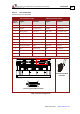
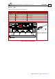
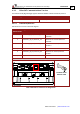
4.3.2.7. I/O Connector
The following table lists the digital input pin assignments. See Section 4.10.1 for full details on
I/O.
I/O Pins Signal Function
1 IN1 High speed programmable input 1 (event capture, home, general
purpose, RLS, FLS, INH, PWM & direction input, pulse & direction input)
2 IN2 High speed programmable input 2 (event capture, home, general
purpose, RLS, FLS, INH, PWM & direction input, pulse & direction input)
7 IN3 High speed programmable input 3 (event capture, home, general
purpose, RLS, FLS, INH, PWM & direction input, pulse & direction input)
8 IN4 High speed programmable input 4 (event capture, home, general
purpose, RLS, FLS, INH, PWM & direction input, pulse & direction input)
11 IN5 High speed programmable input 5 (event capture, home, general
purpose, RLS, FLS, INH, PWM & direction input, pulse & direction input)
12 IN6 High speed programmable input 6 (event capture, home, general
purpose, RLS, FLS, INH, PWM & direction input, pulse & direction input)
or STO OUT Collector in the O version
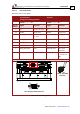
6 INRET1-6 Programmable inputs 1 to 6 return for the S/T/0/1 versions
Programmable positive input 1 to 6 for the APAC version
3 OUT1 Programmable output 1
4 OUT2 Programmable output 2
5 OUT3 Programmable output 3
13 OUT4 Programmable output 4
or STO OUT Emitter in the O version
10, 15 VDD Supply for out 1-4
9, 14 VDDRET Supply return for out 1-4