
Instruction Manual

Gold Drum HV Installation Guide (EtherCAT and CAN) Installation
MAN-G-DRUMHVIG-EC (Ver. 1.202)
|www.elmomc.com
41
Table of Contents
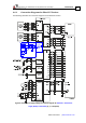
4.3.4. CAN Communications Version
The Gold Drum HV (High Voltage) supports CAN fieldbus industrial network protocol.
Fieldbus Type Product Number
CAN G-DRU XXX/YYYSXXX
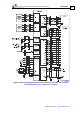
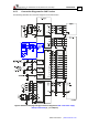
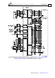
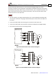
See Section 4.11.2 for the electrical diagram.
Pin on CAN Signal Function
1 CAN_H CAN_H bus line (dominant high)
2 CAN_L CAN_L bus line (dominant low)
3 CAN_RET CAN Return
4, 5 N/A —
6 CAN_SHLD Shield, connected to the RJ plug cover
7 CAN_RET CAN Return
8 N/A —
Pin Positions
Standard CAT5e
Ethernet Cable
Table 9: CAN In/Out Connector Pin Assignments
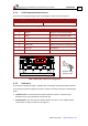
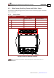
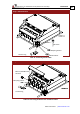
4.3.5. Indicators
The Gold Drum HV (High Voltage) is equipped with several light-emitting diode (LED) indicators.
The Drive Status Indicator red/green dual LED is used for immediate indication of the following
states:
• Initiation state: In this state the LED indicates whether the drive is in the boot state
(blinking red) or in the operational state (steady red).
• Working state: In this state the LED indicates whether the drive is in an amplifier failure
state (red) or is ready to enable the motor (green).