
Instruction Manual


Gold Drum HV Installation Guide (EtherCAT and CAN) Installation
MAN-G-DRUMHVIG-EC (Ver. 1.202)
|www.elmomc.com
62
Table of Contents
4.9.1. Feedback Port A
Port A supports the following sensor inputs:
• Digital Hall sensors
• Incremental encoder or absolute serial encoder, depending on the specific model
Differential pulse-width modulation (PWM) signal input can be connected to port A in the
models that support input from an incremental encoder. The PWM signal can be connected to
the pair of matching + and – encoder channels and is configurable by software.
Differential Pulse & Direction signal inputs can be connected to port A in the models that
support input from an incremental encoder. The signals can be connected to the pair of
matching + and – encoder channels and are configurable by software.
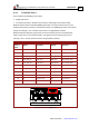
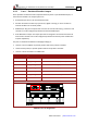
Incremental Encoder Absolute Serial Encoder
Port A
Pins
Signal Function Signal Function
4,12 +5V Encoder +5V supply +5V Encoder +5V supply
3,9,11, 13 SUPRET Common return SUPRET Supply return
6 PortA_ENC_A+ Channel A+ ABS_CLK+ Abs encoder clock +
5 PortA_ENC_A- Channel A- ABS_CLK- Abs encoder clock -
15 PortA_ENC_B+ Channel B+ ABS_DATA+ Abs encoder data +
14 PortA_ENC_B- Channel B- ABS_DATA- Abs encoder data -
8 PortA_ENC_INDEX+ Index+ Reserved Reserved
7 PortA_ENC_INDEX- Index- Reserved Reserved
2 HA Hall sensor A HA Hall sensor A
10 HB Hall sensor B HB Hall sensor B
1 HC Hall sensor C HC Hall sensor C
Pin Positions
Table 18: Port A Pin Assignments