
Manual


Gold Solo Trombone Installation Guide Product Description
MAN-G-SOLTROIG (Ver. 1.3)
www.elmomc.com
18
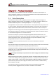
2.3. System Architecture
Isolated Power Stage
Feedback Port A
Feedback Port B
Feedback Out
Port C
Communication
User I/O Interface
Motion
Control
Logic
Incremental
Encoder, Hall
Sensors
(Options E, R)
Serial Encoder,
Hall Sensors
(Options E, R)
Incremental
Encoder
Or
Analog Encoder
(Options E)
Resolver
(Options R)
Encoder
Emulation,
PWM
Digital
Inputs
Digital
Outputs
Analog
Input
CANopen, USB,
(Option S)
EtherCAT, USB,
(Option E)
Main DC Power
Supply
Optional DC
Auxiliary Supply
Motor
PWM
Current
Feedback,
Protection
STO1,
STO2
Or
Or
Or
STO2
Isolation
Boundary
Isolation
Boundary
Figure 1: Gold Solo Trombone System Block Diagram