Gold Trombone Digital Servo Drive Installation Guide EtherCAT and CAN July 2014 (Ver. 1.604) www.elmomc.
Notice This guide is delivered subject to the following conditions and restrictions: • This guide contains proprietary information belonging to Elmo Motion Control Ltd. Such information is supplied solely for the purpose of assisting users of the Gold Trombone servo drive in its installation. • The text and graphics included in this manual are for the purpose of illustration and reference only. The specifications on which they are based are subject to change without notice.
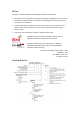
Revision History Version Details 1.0 Initial release 1.1 Major updates to Chapter 3 1.2 Several updates throughout the manual 1.3 Sections 4.3 and 4.3.1: Auxiliary Supply Voltage range: 18 V to 30 V 1.4 Wide ranging changes throughout document to include new pinouts. Removal of the RS-232 option. Added update P/N details on Feedbacks Absolute - included as standard. 1.5 Change the overvoltage in 800 V mode 1.6 Neutral option removed.
Elmo Worldwide Head Office Elmo Motion Control Ltd. 60 Amal St., P.O. Box 3078, Petach Tikva 49516 Israel Tel: +972 (3) 929-2300 • Fax: +972 (3) 929-2322 • info-il@elmomc.com North America Elmo Motion Control Inc. 42 Technology Way, Nashua, NH 03060 USA Tel: +1 (603) 821-9979 • Fax: +1 (603) 821-9943 • info-us@elmomc.com Europe Elmo Motion Control GmbH Hermann-Schwer-Strasse 3, 78048 VS-Villingen Germany Tel: +49 (0) 7721-944 7120 • Fax: +49 (0) 7721-944 7130 • info-de@elmomc.
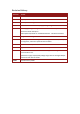
Gold Trombone Installation Guide (EtherCAT and CAN) Table of Contents MAN-G-TROIG-EC (Ver. 1.604) Table of Contents Chapter 1: 1.1. 1.2. 1.3. 1.4. 1.5. Warnings......................................................................................................................... 9 Cautions .......................................................................................................................... 9 Directives and Standards .................................................................
Gold Trombone Installation Guide (EtherCAT and CAN) Table of Contents MAN-G-TROIG-EC (Ver. 1.604) 4.4. 4.5. 4.6. 4.7. 4.8. 4.9. 4.10. 4.11. 4.12. 4.13. 4.3.2.3. Auxiliary Power Connector (J3)..................................................... 27 4.3.2.4. Connector J2 ................................................................................. 28 4.3.2.5. Connector J1 ................................................................................. 31 Mounting the Gold Trombone ..............
Gold Trombone Installation Guide (EtherCAT and CAN) Table of Contents MAN-G-TROIG-EC (Ver. 1.604) 5.3. 5.4. 5.5. 5.6. 5.7. 5.8. 5.9. Control Specifications ................................................................................................... 79 5.3.1. Current Loop .................................................................................................. 79 5.3.2. Velocity Loop .................................................................................................
Gold Trombone Installation Guide (EtherCAT and CAN) Safety Information MAN-G-TROIG-EC (Ver. 1.604) Chapter 1: Safety I nform ation In order to achieve the optimum, safe operation of the Gold Trombone servo drive, it is imperative that you implement the safety procedures included in this installation guide. This information is provided to protect you and to keep your work area safe when operating the Gold Trombone and accompanying equipment.
Gold Trombone Installation Guide (EtherCAT and CAN) Safety Information MAN-G-TROIG-EC (Ver. 1.604) 1.1. Warnings • To avoid electric arcing and hazards to personnel and electrical contacts, never connect/disconnect the servo drive while the power source is on. • Power cables can carry a high voltage, even when the motor is not in motion. Disconnect the Gold Trombone from all voltage sources before it is opened for servicing.
Gold Trombone Installation Guide (EtherCAT and CAN) Safety Information MAN-G-TROIG-EC (Ver. 1.604) 1.3.
Gold Trombone Installation Guide (EtherCAT and CAN) Product Description MAN-G-TROIG-EC (Ver. 1.604) Chapter 2: Product Description This installation guide describes the Gold Trombone servo drive and the steps for its wiring, installation and power-up. Following these guidelines ensures optimal performance of the drive and the system to which it is connected. 2.1.
Gold Trombone Installation Guide (EtherCAT and CAN) Product Description MAN-G-TROIG-EC (Ver. 1.604) 2.2. Product Features Note: The features described in this chapter relate to the range of Gold Trombone models. Depending on the model you have purchased, not all features are available.
Gold Trombone Installation Guide (EtherCAT and CAN) Product Description MAN-G-TROIG-EC (Ver. 1.604) 2.2.2.
Gold Trombone Installation Guide (EtherCAT and CAN) Product Description MAN-G-TROIG-EC (Ver. 1.604) 2.2.5. Feedback Ports Options There are Port A and Port B feedback input ports that are flexible and configurable.
Gold Trombone Installation Guide (EtherCAT and CAN) Product Description MAN-G-TROIG-EC (Ver. 1.604) 2.2.6.
Gold Trombone Installation Guide (EtherCAT and CAN) Product Description MAN-G-TROIG-EC (Ver. 1.604) 2.2.7. Communications • Fast and efficient EtherCAT and CAN networking • EtherCAT Slave per part number: CoE (CAN over EtherCAT) EoE (Ethernet over EtherCAT) FoE (File over EtherCAT) for firmware download Supports Distributed Clock EtherCAT cyclic modes supported down to a cycle time of 250 μs • CAN (DS-301, DS-305, DS-402) per part number. Refer to the section 4.
Gold Trombone Installation Guide (EtherCAT and CAN) Product Description MAN-G-TROIG-EC (Ver. 1.604) • Optional functions: • Fast output compare (for one output only) Brake control Amplifier fault indication General purpose Servo enable indication PWM current command output for torque and velocity 2.2.10.
Gold Trombone Installation Guide (EtherCAT and CAN) Product Description MAN-G-TROIG-EC (Ver. 1.604) 2.2.14.
Product Description Gold Trombone Installation Guide (EtherCAT and CAN) MAN-G-TROIG-EC (Ver. 1.604) 2.3.
Gold Trombone Installation Guide (EtherCAT and CAN) Product Description MAN-G-TROIG-EC (Ver. 1.604) 2.4. How to Use this Guide In order to install and operate your Elmo Gold Trombone servo drive, you will use this manual in conjunction with a set of Elmo documentation.
Technical Information Gold Trombone Installation Guide (EtherCAT and CAN) 21 MAN-G-TROIG-EC (Ver. 1.604) Chapter 3: Technical I nform ation 3.1.
Gold Trombone Installation Guide (EtherCAT and CAN) Technical Information MAN-G-TROIG-EC (Ver. 1.604) Note on current ratings: The current ratings of the Gold Trombone are given in units of DC amperes (ratings that are used for trapezoidal commutation or DC motors). The RMS (sinusoidal commutation) value is the DC value divided by 1.41. 3.1.1.
Installation Gold Trombone Installation Guide (EtherCAT and CAN) MAN-G-TROIG-EC (Ver. 1.604) Chapter 4: I nstallation The Gold Trombone must be installed in a suitable environment and properly connected to its voltage supplies and the motor. 4.1. Site Requirements You can guarantee the safe operation of the Gold Trombone by ensuring that it is installed in an appropriate environment.
Gold Trombone Installation Guide (EtherCAT and CAN) Installation MAN-G-TROIG-EC (Ver. 1.604) 3. To ensure that the Gold Trombone you have unpacked is the appropriate type for your requirements, locate the part number sticker on the side of the Gold Trombone. It looks like this: 4. Verify that the Gold Trombone type is the one that you ordered, and ensure that the voltage meets your specific requirements. The part number at the top gives the type designation as follows: www.elmomc.
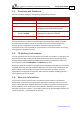
Gold Trombone Installation Guide (EtherCAT and CAN) Installation MAN-G-TROIG-EC (Ver. 1.604) 4.3. Connectors The Gold Trombone has 9 connectors. 4.3.1. Port Connector Types Pins Type Function 1.27 mm pitch 0.41 mm sq Analog Input, Feedback 2 mm pitch 0.
Gold Trombone Installation Guide (EtherCAT and CAN) Installation MAN-G-TROIG-EC (Ver. 1.604) 4.3.2. Pinouts The pinouts in this section describe the function of each pin in the Gold Trombone connectors that are listed in Table 1. 4.3.2.1. Motor Power For full details about connecting motor power see Section 4.7.1.
Installation Gold Trombone Installation Guide (EtherCAT and CAN) MAN-G-TROIG-EC (Ver. 1.604) 4.3.2.3. Auxiliary Power Connector (J3) For full details about connecting auxiliary power, see Section 4.7.3. Pin (J3) Function 1 +24 V Auxiliary Supply Input Positive 2 24 V RET Auxiliary Supply Input Return Pin Positions Connector Type: 2 mm pitch 0.51 mm sq Table 4: Auxiliary 24 VDC Backup Supply Pins and Polarity www.elmomc.
Gold Trombone Installation Guide (EtherCAT and CAN) Installation MAN-G-TROIG-EC (Ver. 1.604) 4.3.2.4. Connector J2 Feedback, Analog input, communications Connector Type: 1.27 mm pitch 0.41 mm sq For full details about connecting feedback port A see Section 4.9.1. For full details about connecting feedback port B see Section 4.9.2. For full details about connecting feedback port C see Section 4.9.3. For full details about connecting analog input see Section 4.10.3.
Installation Gold Trombone Installation Guide (EtherCAT and CAN) MAN-G-TROIG-EC (Ver. 1.
Installation Gold Trombone Installation Guide (EtherCAT and CAN) MAN-G-TROIG-EC (Ver. 1.
Gold Trombone Installation Guide (EtherCAT and CAN) Installation MAN-G-TROIG-EC (Ver. 1.604) 4.3.2.5. Connector J1 Digital Inputs, Digital Outputs, STO, Amplifier and Communication LEDs, Encoder Supply Connector Type: 1.27 mm pitch 0.41 mm sq For full details about connecting digital input see Section 4.10.3. For full details about connecting digital output see Section 4.10.2.
Gold Trombone Installation Guide (EtherCAT and CAN) Installation MAN-G-TROIG-EC (Ver. 1.
Gold Trombone Installation Guide (EtherCAT and CAN) Installation MAN-G-TROIG-EC (Ver. 1.604) 4.4. Mounting the Gold Trombone The Gold Trombone is designed for mounting on a printed circuit board (PCB). It is connected by 1.27 mm pitch 0.41 mm square pins and 2.54 mm pitch 0.64 mm square pins. When integrating the Gold Trombone into a PCB, be sure to leave about 1 cm (0.4") outward from the heatsink to enable free convection of the air around the Gold Trombone.
Installation Gold Trombone Installation Guide (EtherCAT and CAN) MAN-G-TROIG-EC (Ver. 1.604) 4.5. Integrating the Gold Trombone on a PCB The Gold Trombone is designed to be mounted on a PCB, either by soldering its pins directly to the PCB or by using suitable socket connectors. In both cases the following rules apply: 4.5.1. Traces 1. The size of the traces on the PCB (thickness and width) is determined by the current carrying capacity required by the application.
Gold Trombone Installation Guide (EtherCAT and CAN) Installation MAN-G-TROIG-EC (Ver. 1.604) 4.5.2. Grounds and Returns The “Returns” of the Gold Trombone are structured internally in a star configuration.
Gold Trombone Installation Guide (EtherCAT and CAN) Installation MAN-G-TROIG-EC (Ver. 1.604) 7. Under normal operating conditions, the PE trace carries no current. The only time these traces carry current is under abnormal conditions (such as when the device has become a potential shock or fire hazard while conducting external EMI interferences directly to ground). When connected properly the PE trace prevents these hazards from affecting the drive. 4.6.
Gold Trombone Installation Guide (EtherCAT and CAN) Installation MAN-G-TROIG-EC (Ver. 1.604) Figure 3: Gold Trombone Connection Diagram for EtherCAT – with Backup Functionality (S or T Model Drive) www.elmomc.
Gold Trombone Installation Guide (EtherCAT and CAN) Installation MAN-G-TROIG-EC (Ver. 1.604) Figure 4: Gold Trombone Connection Diagram for EtherCAT – 400 V without Backup Functions (0 or 1 Suffix) www.elmomc.
Gold Trombone Installation Guide (EtherCAT and CAN) Installation MAN-G-TROIG-EC (Ver. 1.604) Figure 5: Gold Trombone Connection Diagram for CAN – with Backup Functionality (S or T Model Drive) www.elmomc.
Gold Trombone Installation Guide (EtherCAT and CAN) Installation MAN-G-TROIG-EC (Ver. 1.604) Figure 6: Gold Trombone Connection Diagram for CAN – 400 V without Backup Functions (0 or 1 Suffix) www.elmomc.
Installation Gold Trombone Installation Guide (EtherCAT and CAN) MAN-G-TROIG-EC (Ver. 1.604) 4.7. Main Power, Motor Power and Auxiliary Power The Gold Trombone receives power from main and auxiliary supplies and delivers power to the motor. Note: There are multiple voltage ratings of the Gold Trombone (80 V to 780 V), so you must use the correct power supply according to the maximum operating voltage of the Gold Trombone. See Section Chapter 3: Technical Information 4.7.1.
Installation Gold Trombone Installation Guide (EtherCAT and CAN) MAN-G-TROIG-EC (Ver. 1.604) Figure 8: DC Brushed Motor Power Connection Diagram Notes: • For best immunity, it is highly recommended to use a 4-wire shielded (not twisted) cable for the motor connection. The gauge is determined by the actual current consumption of the motor. • Connect the cable shield to the closest ground connection at the motor end. • Connect the cable shield to the closest PE terminal of the Gold Trombone.
Gold Trombone Installation Guide (EtherCAT and CAN) Installation MAN-G-TROIG-EC (Ver. 1.604) The following sections contain topology recommendations for implementing three-phase and single-phase supply chains. The power stage of the Gold Trombone is fully isolated from the other sections of the Gold Trombone, such as the control-stage and the heat-sink.
Installation Gold Trombone Installation Guide (EtherCAT and CAN) MAN-G-TROIG-EC (Ver. 1.604) 4.7.2.1.a Three-Phase Direct-to-Mains Connection Topology Figure 9: Non-Isolated Three-Phase Connection Topology Caution: • Do not connect VN- to PE. In a direct-to-mains connection the VN- must not be connected to the PE, as this will cause irreparable damage to the system. • Take care and note that in a direct-to-mains connection the Neutral point is not the most negative voltage level.
Installation Gold Trombone Installation Guide (EtherCAT and CAN) MAN-G-TROIG-EC (Ver. 1.604) 4.7.2.1.b Single-Phase Direct-to-Mains Connection Topology Figure 10: Non-Isolated Single-Phase Connection Topology The Power Supply is connected directly to the mains AC line. Warning: • Do not connect VN- to PE. In a direct-to-mains connection the VN- must not be connected to the PE, as this will cause irreparable damage to the system.
Gold Trombone Installation Guide (EtherCAT and CAN) Installation MAN-G-TROIG-EC (Ver. 1.604) 4.7.2.1.c Multiple Connections Topology In a multi-axis application it is likely that a single power supply can feed several drives in parallel. This topology is efficient and cost saving, by reducing the number of power supplies and the amount of wiring. Most importantly it utilizes an energy sharing environment among all the drives that share the same DC bus network.
Installation Gold Trombone Installation Guide (EtherCAT and CAN) MAN-G-TROIG-EC (Ver. 1.604) 4.7.2.2. Battery Power Supply Figure 12: Battery Connection Topology Caution: When using batteries, it is recommended to connect the negative pole to the PE. When doing so, the charger of the battery must be isolated from the mains by an isolation transformer. 4.7.3.
Installation Gold Trombone Installation Guide (EtherCAT and CAN) MAN-G-TROIG-EC (Ver. 1.604) If backup functionality is required to store control parameters in the event of a mains power outage, then an S or T-model Gold Trombone should be used, with an external 24 VDC isolated supply connected to it. Note that the S or T-model Gold Trombone always requires an external 24 VDC power supply, regardless of whether or not backup functionality is required.
Installation Gold Trombone Installation Guide (EtherCAT and CAN) MAN-G-TROIG-EC (Ver. 1.604) 4.8. STO (Safe Torque Off) Inputs (J1) Activation of Safe Torque Off causes the drive to stop providing power that can cause rotation (or motion in the case of a linear motor) to the motor. This function may be used to prevent unexpected motor rotation (of brushless DC motors) without disconnecting the drive from the power supply.
Installation Gold Trombone Installation Guide (EtherCAT and CAN) MAN-G-TROIG-EC (Ver. 1.604) Figure 14: STO Input Connection – PLC Option for S or 0 Suffixes Figure 15: Safety Input Connection – TTL Option for T or 1 Suffixes www.elmomc.
Installation Gold Trombone Installation Guide (EtherCAT and CAN) MAN-G-TROIG-EC (Ver. 1.604) 4.9. Feedback Port B Port A Port C Figure 16: Feedback Ports on J2 The Gold Trombone has two configurable motion sensor input ports, namely, Port A and Port B, and the emulated buffered output Port C. Motion sensors from the motor being controlled and from other sources can be connected to any of the available inputs on Port A or Port B. Software configuration designates each input a role, e.g.
Installation Gold Trombone Installation Guide (EtherCAT and CAN) MAN-G-TROIG-EC (Ver. 1.
Gold Trombone Installation Guide (EtherCAT and CAN) Installation MAN-G-TROIG-EC (Ver. 1.604) 4.9.1.1. Incremental Encoder Connection Diagram Figure 17: Port A Incremental Encoder Input – Recommended Connection Diagram www.elmomc.
Gold Trombone Installation Guide (EtherCAT and CAN) Installation MAN-G-TROIG-EC (Ver. 1.604) 4.9.1.2. Absolute Serial Encoder Connection Diagram Figure 18: Absolute Serial Encoder – Recommended Connection Diagram for Sensors Supporting Data/Clock (e.g., Biss/SSI/EnDAT/etc.) www.elmomc.
Gold Trombone Installation Guide (EtherCAT and CAN) Installation MAN-G-TROIG-EC (Ver. 1.604) Figure 19: Absolute Serial Encoder – Recommended Connection Diagram for Sensors Supporting Data Line Only (NRZ types, e.g., Panasonic / Mitutoyo / etc.) 4.9.1.3. Hall Sensor Connection Diagram Figure 20: Hall Sensors Connection Diagram www.elmomc.
Installation Gold Trombone Installation Guide (EtherCAT and CAN) MAN-G-TROIG-EC (Ver. 1.604) 4.9.2. Port B (J2, J1) Port B supports the following sensors: • Incremental encoder, interpolated analog encoder or as analog Hall sensors Or: • Resolver (separate hardware option) Differential PWM signal input can be connected to port B in the models that support input from an incremental encoder.
Gold Trombone Installation Guide (EtherCAT and CAN) Installation MAN-G-TROIG-EC (Ver. 1.604) 4.9.2.1. Incremental Encoder Connection Diagram Figure 21: Port B Incremental Encoder Input – Recommended Connection Diagram www.elmomc.
Gold Trombone Installation Guide (EtherCAT and CAN) Installation MAN-G-TROIG-EC (Ver. 1.604) 4.9.2.2. Interpolated Analog Encoder Connection Diagram Figure 22: Port B - Interpolated Analog Encoder Connection Diagram www.elmomc.
Gold Trombone Installation Guide (EtherCAT and CAN) Installation MAN-G-TROIG-EC (Ver. 1.604) 4.9.2.3. Resolver Connection Diagram Figure 23: Port B – Resolver Connection Diagram 4.9.3. Port C – Emulated Encoder Output (J2) Port C provides emulated encoder output derived from port A or port B feedback inputs, or from internal variables.
Installation Gold Trombone Installation Guide (EtherCAT and CAN) MAN-G-TROIG-EC (Ver. 1.
Gold Trombone Installation Guide (EtherCAT and CAN) Installation MAN-G-TROIG-EC (Ver. 1.604) 4.10. User I/Os The Gold Trombone has six programmable digital inputs (J1), four digital outputs (J1) and one analog input (J2). 4.10.1. Digital Inputs (J1) Each of the pins below can function as an independent input.
Gold Trombone Installation Guide (EtherCAT and CAN) Installation MAN-G-TROIG-EC (Ver. 1.604) Figure 25: Digital Input PLC Mode Connection Diagram for S or 0 Suffixes www.elmomc.
Gold Trombone Installation Guide (EtherCAT and CAN) Installation MAN-G-TROIG-EC (Ver. 1.604) Figure 26: Digital Input TTL Mode Connection Diagram for T or 1 Suffixes www.elmomc.
Gold Trombone Installation Guide (EtherCAT and CAN) Installation MAN-G-TROIG-EC (Ver. 1.604) 4.10.2. Digital Outputs (J1) The outputs conform to the PLC standard. TTL configuration is available upon request.
Gold Trombone Installation Guide (EtherCAT and CAN) Installation MAN-G-TROIG-EC (Ver. 1.604) Figure 27: Digital Output Connection Diagram – PLC Option for S or 0 Suffixes www.elmomc.
Gold Trombone Installation Guide (EtherCAT and CAN) Installation MAN-G-TROIG-EC (Ver. 1.604) Figure 28: Digital Output Connection Diagram – TTL Option for T or 1 Suffixes www.elmomc.
Installation Gold Trombone Installation Guide (EtherCAT and CAN) MAN-G-TROIG-EC (Ver. 1.604) 4.10.3. Input (J2) An analog user input can be configured by software to be used as either tachometer velocity sensor input or potentiometer position feedback. Pin (J2) Signal Function 22 ANALOG1+ Analog input 1+ 24 ANALOG1- Analog input 1- 20 ANLRET Analog ground Table 18: Analog Input Pin Assignment Figure 29: Analog Input with Single-Ended Source www.elmomc.
Gold Trombone Installation Guide (EtherCAT and CAN) Installation MAN-G-TROIG-EC (Ver. 1.604) 4.11. Communications The communication interface may differ according to the user’s hardware. The Gold Trombone can communicate using the following options: Standard EtherCAT G-TROXXX/YYYSXX G-TROXXX/YYYEXX CAN EtherCAT USB 2.0 USB 2.0 Table 19: Gold Trombone Communication Options For ease of setup and diagnostics of CAN communication, and CAN can be used simultaneously.
Gold Trombone Installation Guide (EtherCAT and CAN) Installation MAN-G-TROIG-EC (Ver. 1.604) Figure 30: CAN Network Diagram Caution: When installing CAN communication, ensure that each servo drive is allocated a unique ID. Otherwise, the CAN network may “hang”. www.elmomc.
Installation Gold Trombone Installation Guide (EtherCAT and CAN) MAN-G-TROIG-EC (Ver. 1.604) 4.11.2. USB 2.0 Communication (J2) The USB network consists of a Host controller and multiple devices. The Gold Trombone is a USB device. To connect the USB communication cable: 1. Connect the shield to the ground of the host (PC). Usually, this connection is soldered internally inside the connector at the PC end. You can use the drain wire to facilitate connection. 2.
Gold Trombone Installation Guide (EtherCAT and CAN) Installation MAN-G-TROIG-EC (Ver. 1.604) 4.11.3. EtherCAT Communication (J2) To use EtherCAT and Ethernet communication with the Gold Trombone, it is required to use an isolation transformer. The most common solution is to use RJ-45 connectors that include transformer isolation. This section describes how to connect the Gold Trombone’s EtherCAT interface using the above mentioned connectors. Notes for EtherCAT communication: 1.
Gold Trombone Installation Guide (EtherCAT and CAN) Installation MAN-G-TROIG-EC (Ver. 1.604) Figure 32: EtherCAT Connection Schematic Diagram www.elmomc.
Gold Trombone Installation Guide (EtherCAT and CAN) Installation MAN-G-TROIG-EC (Ver. 1.604) Note: The diagram above ignores line interface for simplicity. When connecting several EtherCAT devices in a network, the EtherCAT master must always be the first device in the network. The output of each device is connected to the input of the next device. The output of the last device may remain disconnected.
Installation Gold Trombone Installation Guide (EtherCAT and CAN) MAN-G-TROIG-EC (Ver. 1.604) Pin (J2) Signal Function 26 3.3 V 3.
Gold Trombone Installation Guide (EtherCAT and CAN) Installation MAN-G-TROIG-EC (Ver. 1.604) 4.11.5. EtherCAT/Ethernet Line Interface Ethernet transceivers require either isolation transformers or capacitor coupling for proper functioning. The Gold Trombone unit does not include such isolation, therefore you must take this into consideration when designing the integration board. In Sections 4.11.3 and 4.11.
Gold Trombone Installation Guide (EtherCAT and CAN) Installation MAN-G-TROIG-EC (Ver. 1.604) 4.13. Heat Dissipation The best way to dissipate heat from the Gold Trombone is to mount it so that its heatsink faces up. For best results leave approximately 10 mm of space between the Gold Trombone‘s heatsink and any other assembly. 4.13.1. Gold Trombone Thermal Data • Heat dissipation capability (θ): approximately 5.
Installation Gold Trombone Installation Guide (EtherCAT and CAN) MAN-G-TROIG-EC (Ver. 1.604) Figure 37: Dissipation versus Current Graph for 330 VDC 4.13.3. How to Use the Charts The power dissipation in the chart includes the losses of the rectifying bridge. Regarding Figure 36 and Figure 37, the following should be noted: DC Bus Voltage (VDC) Rectified Voltage (VAC) 560 3X400 680 3X480 330 3X230 The charts above are based upon theoretical worst-case conditions.
Gold Trombone Installation Guide (EtherCAT and CAN) Technical Specifications MAN-G-TROIG-EC (Ver. 1.604) Chapter 5: Technical Specifications This chapter provides detailed technical information regarding the Gold Trombone. This includes its dimensions, power ratings, the environmental conditions under which it can be used, the standards to which it complies and other specifications. 5.1. Gold Trombone Dimensions www.elmomc.
Gold Trombone Installation Guide (EtherCAT and CAN) Technical Specifications MAN-G-TROIG-EC (Ver. 1.604) 5.2. Environmental Conditions Feature Details Ambient operating temperature 0 °C to 40 °C (32 °F to 104 °F) Storage temperature -20 °C to 85 °C (-4 °F to 185 °F) Maximum Altitude 2,000 m (6562 feet) Maximum non-condensing humidity 90% Protection level IP64 5.3. Control Specifications 5.3.1.
Gold Trombone Installation Guide (EtherCAT and CAN) Technical Specifications MAN-G-TROIG-EC (Ver. 1.604) 5.3.2. Velocity Loop Feature Details Controller type PI + Four advanced filters + Two advanced gain scheduling filters Velocity control • Fully digital • Programmable PI and feed forward control filters • On-the-fly gain scheduling according to either speed or position command or feedback.
Gold Trombone Installation Guide (EtherCAT and CAN) Technical Specifications MAN-G-TROIG-EC (Ver. 1.604) 5.4. Feedback 5.4.1. Feedback Supply Voltage The Gold Trombone has two feedback ports (Main and Auxiliary). The Gold Trombone supplies voltage only to the main feedback device and to the auxiliary feedback device if needed. Feature Details Encoder supply voltage 5 V ± 5% @ 2 x 200 mA (maximum) 5.4.2.
Gold Trombone Installation Guide (EtherCAT and CAN) Technical Specifications MAN-G-TROIG-EC (Ver. 1.604) 5.4.2.2. Digital Halls Feature Details • HA, HB, HC Hall inputs • Single ended inputs • Built in hysteresis of 1 V for noise immunity Input voltage Nominal operating range: 0 V < VIn_Hall < 5 V Maximum absolute: -1 V < VIn_Hall < 15 V High level input voltage: V InHigh > 2.
Gold Trombone Installation Guide (EtherCAT and CAN) Technical Specifications MAN-G-TROIG-EC (Ver. 1.604) 5.4.2.4. Resolver Feature Details Resolver format • Sine/Cosine • Differential Input resistance Differential 2.49 kΩ Resolution Programmable: 10 to 15 bits Maximum electrical frequency (RPS) 512 revolutions/sec Resolver transfer ratio 0.
Gold Trombone Installation Guide (EtherCAT and CAN) Technical Specifications MAN-G-TROIG-EC (Ver. 1.604) 5.4.3. Port C Feedback Output Feature Emulated output Details • A, B, Index • Differential Interface RS-422 Output current capability Maximum output current: IOH (max) = 2 mA High level output voltage: VOH > 3.0 V Minimum output current: IOL = 2 mA Low level output voltage: VOL < 0.
Gold Trombone Installation Guide (EtherCAT and CAN) Technical Specifications MAN-G-TROIG-EC (Ver. 1.604) 5.5. I/Os The Gold Trombone has: • 6 Digital Inputs • 4 Digital Outputs • 1 Analog Input 5.5.1. Digital Input Interfaces – TTL Mode Feature Details Suffix applicable T or 1 Type of input Optically isolated Input current for all inputs Iin = 3.8 mA @ Vin = 5 V High-level input voltage 2.4 V < Vin < 15 V, 5 V typical Low-level input voltage 0 V < Vin < 0.
Gold Trombone Installation Guide (EtherCAT and CAN) Technical Specifications MAN-G-TROIG-EC (Ver. 1.604) 5.5.2.
Gold Trombone Installation Guide (EtherCAT and CAN) Technical Specifications MAN-G-TROIG-EC (Ver. 1.604) 5.5.3. Digital Output Interface – PLC Mode Feature Details Suffix applicable S or 0 Type of output Optically isolated source Supply output (VDD) 12 V to 30 V Maximum output current Iout (max) (Vout = Low) Iout (max) ≤ 500 mA for output 1 Iout(max) ≤ 250 mA for outputs 2 to 4 VOL at maximum output voltage (low level) Vout (on) ≤ 0.
Gold Trombone Installation Guide (EtherCAT and CAN) Technical Specifications MAN-G-TROIG-EC (Ver. 1.604) 5.5.4. Digital Output Interface – TTL Mode Feature Details Suffix applicable T or 1 • Optically isolated Type of output • Source/Sink Supply output (VDD) 5 V to 15 V Max. output current Iout (max) (Vout = Low) 7 mA VOL at maximum output voltage (low level) Vout (on) ≤ 0.4 V Executable time 0< T< 250 µsec Figure 42: Digital Output Schematic 5.5.5.
Gold Trombone Installation Guide (EtherCAT and CAN) Technical Specifications MAN-G-TROIG-EC (Ver. 1.604) 5.6. Safe Torque Off (STO) The Gold Trombone has two STO (Safe Torque Off) inputs. 5.6.1. STO Input Interfaces – TTL Mode Feature Details Suffix applicable T or 1 Type of input Optically isolated Input current for all inputs Iin = 3.8 mA @ Vin = 5 V High-level input voltage 2.4 V < Vin < 15 V, 5 V typical Low-level input voltage 0 V < Vin < 0.
Gold Trombone Installation Guide (EtherCAT and CAN) Technical Specifications MAN-G-TROIG-EC (Ver. 1.604) 5.7. Communications Specification Details CAN CAN bus Signals: • CAN_H, CAN_L, CAN_COMRET • Maximum Baud Rate of 1 Mbit/sec. Version: • DS 301 v4.
Gold Trombone Installation Guide (EtherCAT and CAN) Technical Specifications MAN-G-TROIG-EC (Ver. 1.604) 5.9. Compliance with Standards Specification Details Quality Assurance ISO 9001:2008 Quality Management Design Approved IEC/EN 61800-5-1, Safety Printed wiring for electronic equipment (clearance, creepage, spacing, conductors sizing, etc.) MIL-HDBK- 217F Reliability prediction of electronic equipment (rating, de-rating, stress, etc.
Gold Trombone Installation Guide (EtherCAT and CAN) Technical Specifications MAN-G-TROIG-EC (Ver. 1.