
User guide

Gold Trombone Installation Guide (EtherCAT and CAN) Installation
MAN-G-TROIG-EC (Ver. 1.604)
www.elmomc.com
61
4.10. User I/Os
The Gold Trombone has six programmable digital inputs (J1), four digital outputs (J1) and one
analog input (J2).
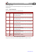
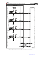
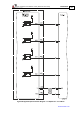
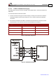
4.10.1. Digital Inputs (J1)
Each of the pins below can function as an independent input.
Pin (J1) Signal Function
6 IN1 High speed programmable input 1
(event capture, home, general purpose, RLS, FLS, INH, PWM & dir
input, pulse & dir input)
7 IN2 High speed programmable input 2
(event capture, home, general purpose, RLS, FLS, INH, PWM & dir
input, pulse & dir input)
8 IN3 High speed programmable input 3
(event capture, home, general purpose, RLS, FLS, INH, PWM & dir
input, pulse & dir input)
9 IN4 High speed programmable input 4
(event capture, home, general purpose, RLS, FLS, INH, PWM & dir
input, pulse & dir input)
10 IN5 High speed programmable input 5
(event capture, home, general purpose, RLS, FLS, INH, PWM & dir
input, pulse & dir input)
11 IN6 High speed programmable input 6
(event capture, home, general purpose, RLS, FLS, INH, PWM & dir
input, pulse & dir input)
5 INRET1-6 Programmable inputs 1 - 6 return
Table 16: Digital Input Pin Assignments
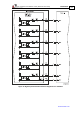
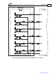
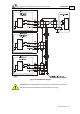
See Figure 25 for the PLC option connection and Figure 26 for the TTL option connection.