
Manual


Table Of Contents
- Chapter 1: This Installation Guide
- Chapter 2: Safety Information
- Chapter 3: Product Description
- Chapter 4: Technical Information
- Chapter 5: Installation
- Chapter 6: Gold Tuba Connection Diagrams
- Chapter 7: Wiring
- 7.1. Basic Recommendations
- 7.2. Motor Power Connector Pinouts
- 7.3. Main Power
- 7.4. Auxiliary Power
- 7.5. Port A
- 7.6. Port B
- 7.7. Port C and Analog Input
- 7.8. STO Connector
- 7.9. Digital Inputs and Outputs
- 7.10. USB 2.0
- 7.11. Network I/O
- 7.12. Smart Fan
- 7.13. Drive Status Indicator
- 7.14. EtherCAT Communications Version
- 7.15. CAN Communications Version
- Chapter 8: Powering Up
- Chapter 9: Dimensions
Gold Tuba Installation Guide
MAN-G-TUBIG-EC (Ver. 1.201)
|www.elmomc.com
29
Table of Contents
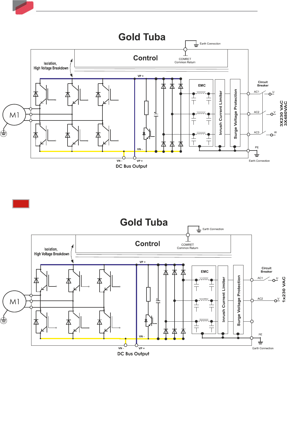
7.3.1.1. Three-Phase Direct-to-Mains Connection Topology
Figure 11: Non-Isolated Three-Phase Source - Connection Topology
7.3.1.2. Single-Phase Direct-to-Mains Connection Topology
Note: The single-phase connection is suitable for G-TUB30/230 model only.
Figure 12: Non-Isolated Single-Phase Source - Connection Topology
7.3.1.3. Multiple Connections Topology
In a multi-axis application it is likely that a single power supply can feed several drives in parallel.
The Gold Tuba can be used to supply power to several drives through its DC output VP+ and VN-
connections, directly to the other drives. This is referred to as the DC-Link.