
Manual


Table Of Contents
- Chapter 1: This Installation Guide
- Chapter 2: Safety Information
- Chapter 3: Product Description
- Chapter 4: Technical Information
- Chapter 5: Installation
- Chapter 6: Gold Tuba Connection Diagrams
- Chapter 7: Wiring
- 7.1. Basic Recommendations
- 7.2. Motor Power Connector Pinouts
- 7.3. Main Power
- 7.4. Auxiliary Power
- 7.5. Port A
- 7.6. Port B
- 7.7. Port C and Analog Input
- 7.8. STO Connector
- 7.9. Digital Inputs and Outputs
- 7.10. USB 2.0
- 7.11. Network I/O
- 7.12. Smart Fan
- 7.13. Drive Status Indicator
- 7.14. EtherCAT Communications Version
- 7.15. CAN Communications Version
- Chapter 8: Powering Up
- Chapter 9: Dimensions
Gold Tuba Installation Guide
MAN-G-TUBIG-EC (Ver. 1.201)
|www.elmomc.com
30
Table of Contents
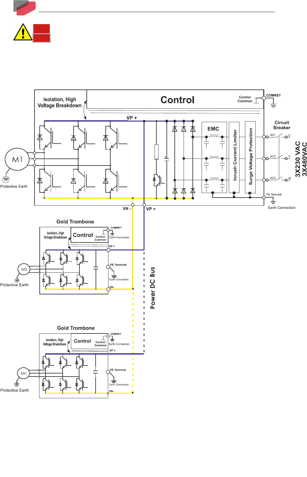
Note:
These drive(s) must be Isolated DC drives.
This topology is efficient and cost saving, by reducing the number of power supplies and the
amount of wiring. Most importantly it utilizes an energy sharing environment among all the drives
that share the same DC bus network. In addition, the G-Tuba internal shunt regulator services the
complete network.
Figure 13: Non-Isolated Three-Phase Source - Multiple Connection Topology
7.3.2. Shunt Regulator
A shunt regulator is included in the Gold Tuba. The shunt regulator is a switching type, wherein
dissipative elements (power resistors) are switched across the DC bus, whenever the voltage
reaches a predetermined level. The function of the shunt regulator is to regulate the voltage of the