
Manual


Table Of Contents
- Chapter 1: This Installation Guide
- Chapter 2: Safety Information
- Chapter 3: Product Description
- Chapter 4: Technical Information
- Chapter 5: Installation
- Chapter 6: Gold Tuba Connection Diagrams
- Chapter 7: Wiring
- 7.1. Basic Recommendations
- 7.2. Motor Power Connector Pinouts
- 7.3. Main Power
- 7.4. Auxiliary Power
- 7.5. Port A
- 7.6. Port B
- 7.7. Port C and Analog Input
- 7.8. STO Connector
- 7.9. Digital Inputs and Outputs
- 7.10. USB 2.0
- 7.11. Network I/O
- 7.12. Smart Fan
- 7.13. Drive Status Indicator
- 7.14. EtherCAT Communications Version
- 7.15. CAN Communications Version
- Chapter 8: Powering Up
- Chapter 9: Dimensions
Gold Tuba Installation Guide
MAN-G-TUBIG-EC (Ver. 1.201)
|www.elmomc.com
32
Table of Contents
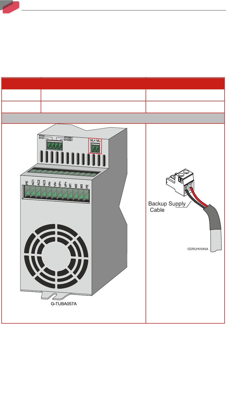
7.4. Auxiliary Power
Backup functionality is required to store control parameters in the event of a mains power outage.
Note that the Gold Tuba always requires an external 24 VDC power supply, regardless of whether or
not backup functionality is required.
See Section 7.3.3 for full details.
Pin Function Cable
VL+ +24 V Auxiliary Supply Input Positive Auxiliary Power
VL- 24 V RET Auxiliary Supply Input Return Auxiliary Power
Pin Positions
2-Pin Pluggable 3.81 mm Phoenix Connector
2-Pin Phoenix Plug-in
Connector
Connect the auxiliary 24 VDC power supply as described below.
To connect the 24 VDC power supply:
1. Use a 24 AWG twisted pair shielded cable. The shield should have copper braid.
2. The source of the 24VDC power supply must be isolated from the mains.
3. For safety and EMI reasons, connect the return of the 24 VDC power supply to the closest
ground (PE) in the power supply side.
4. Connect the cable shield to the closest ground (PE) near the power source.
5. Before applying power, first verify that the polarity of the connection is correct.