
Manual


Table Of Contents
- Chapter 1: This Installation Guide
- Chapter 2: Safety Information
- Chapter 3: Product Description
- Chapter 4: Technical Information
- Chapter 5: Installation
- Chapter 6: Gold Tuba Connection Diagrams
- Chapter 7: Wiring
- 7.1. Basic Recommendations
- 7.2. Motor Power Connector Pinouts
- 7.3. Main Power
- 7.4. Auxiliary Power
- 7.5. Port A
- 7.6. Port B
- 7.7. Port C and Analog Input
- 7.8. STO Connector
- 7.9. Digital Inputs and Outputs
- 7.10. USB 2.0
- 7.11. Network I/O
- 7.12. Smart Fan
- 7.13. Drive Status Indicator
- 7.14. EtherCAT Communications Version
- 7.15. CAN Communications Version
- Chapter 8: Powering Up
- Chapter 9: Dimensions
Gold Tuba Installation Guide
MAN-G-TUBIG-EC (Ver. 1.201)
|www.elmomc.com
47
Table of Contents
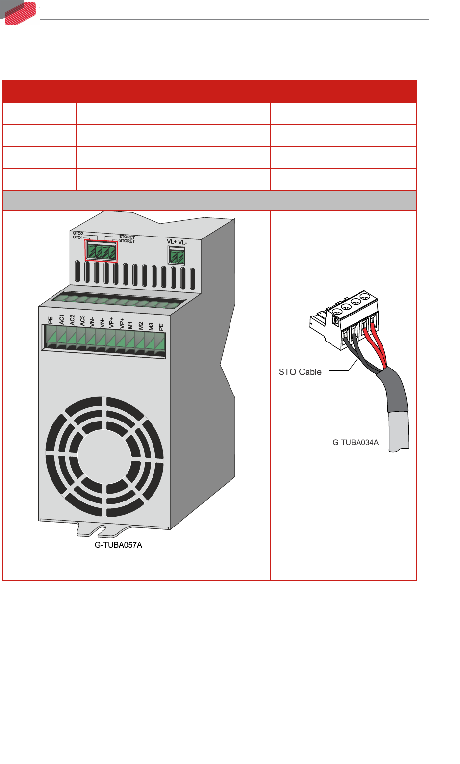
7.8. STO Connector
See Chapter 9 in the in the MAN-G-Panel Mounted Drives Hardware manual for full details.
Pin Function Cable
STO1 STO1 Input STO cable
STO2 STO2 Input STO cable
STORET STO Return Signal STO cable
STORET STO Return Signal STO cable
Pin Positions
4-Pin Pluggable 3.81 mm Phoenix Connector
4-Pin Phoenix Plug-in
Connector