
Manual


Table Of Contents
- Chapter 1: This Installation Guide
- Chapter 2: Safety Information
- Chapter 3: Product Description
- Chapter 4: Technical Information
- Chapter 5: Installation
- Chapter 6: Gold Tuba Connection Diagrams
- Chapter 7: Wiring
- 7.1. Basic Recommendations
- 7.2. Motor Power Connector Pinouts
- 7.3. Main Power
- 7.4. Auxiliary Power
- 7.5. Port A
- 7.6. Port B
- 7.7. Port C and Analog Input
- 7.8. STO Connector
- 7.9. Digital Inputs and Outputs
- 7.10. USB 2.0
- 7.11. Network I/O
- 7.12. Smart Fan
- 7.13. Drive Status Indicator
- 7.14. EtherCAT Communications Version
- 7.15. CAN Communications Version
- Chapter 8: Powering Up
- Chapter 9: Dimensions
Gold Tuba Installation Guide
MAN-G-TUBIG-EC (Ver. 1.201)
|www.elmomc.com
58
Table of Contents
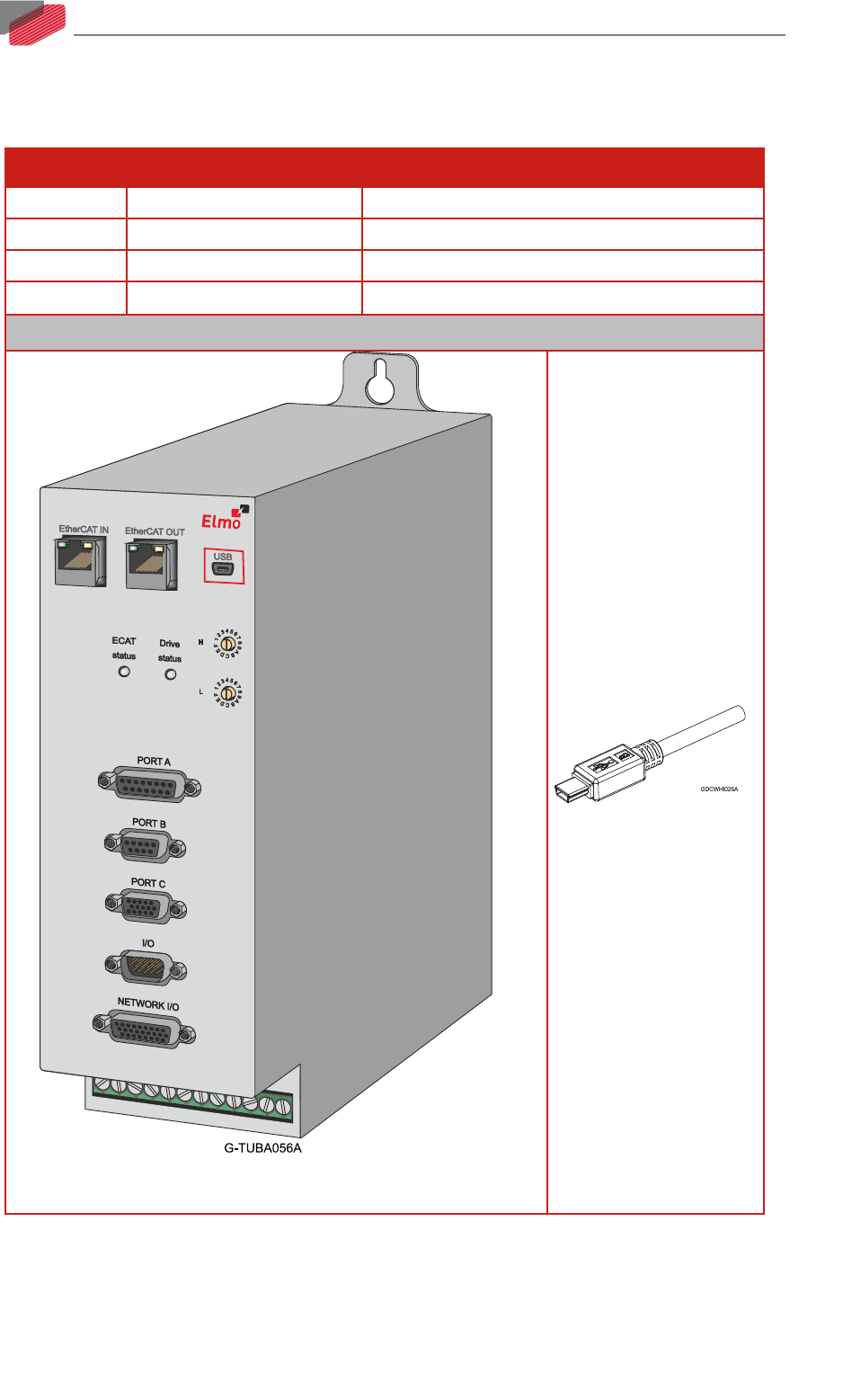
7.10. USB 2.0
See Section 12.1 in the MAN-G-Panel Mounted Drives Hardware manual for full details.
Pin on USB Signal Function
1
USB VBUS
USB VBUS 5V Detector
2
USBD-
USB _N line
3
USBD+
USB _P line
5 USB COMRET USB communication return
Pin Positions
USB Mini B Connecter
USB Device Mini B Plug
Table 6: USB 2.0 Pin Assignments