
Manual


Table Of Contents
- Chapter 1: This Installation Guide
- Chapter 2: Safety Information
- Chapter 3: Product Description
- Chapter 4: Technical Information
- Chapter 5: Installation
- Chapter 6: Gold Tuba Connection Diagrams
- Chapter 7: Wiring
- 7.1. Basic Recommendations
- 7.2. Motor Power Connector Pinouts
- 7.3. Main Power
- 7.4. Auxiliary Power
- 7.5. Port A
- 7.6. Port B
- 7.7. Port C and Analog Input
- 7.8. STO Connector
- 7.9. Digital Inputs and Outputs
- 7.10. USB 2.0
- 7.11. Network I/O
- 7.12. Smart Fan
- 7.13. Drive Status Indicator
- 7.14. EtherCAT Communications Version
- 7.15. CAN Communications Version
- Chapter 8: Powering Up
- Chapter 9: Dimensions
Gold Tuba Installation Guide
MAN-G-TUBIG-EC (Ver. 1.201)
|www.elmomc.com
73
Table of Contents
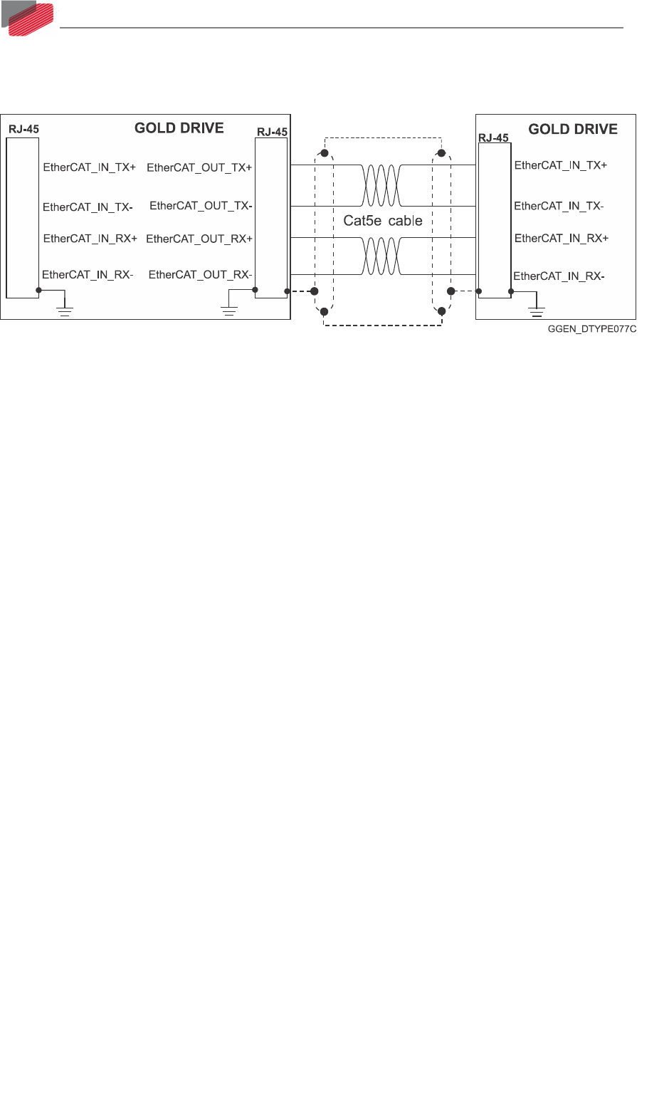
7.14.3. EtherCAT Wiring
Figure 41 describes the wiring diagram for the EtherCAT connections.
Figure 41: EtherCAT RJ-45 Connections
7.14.4. EtherCAT Link Indicators
The Gold Tuba can serve as an EtherCAT slave device. For this purpose it has two RJ-45 connectors,
which are designated as EtherCAT In and EtherCAT Out. Each of these RJ-45 connectors has two
status LEDs. For full details, see Section 12.2 in the MAN-G-Panel Mounted Drives Hardware
manual.