
Manual


Table Of Contents
- Chapter 1: This Installation Guide
- Chapter 2: Safety Information
- Chapter 3: Product Description
- Chapter 4: Technical Information
- Chapter 5: Installation
- Chapter 6: Gold Tuba Connection Diagrams
- Chapter 7: Wiring
- 7.1. Basic Recommendations
- 7.2. Motor Power Connector Pinouts
- 7.3. Main Power
- 7.4. Auxiliary Power
- 7.5. Port A
- 7.6. Port B
- 7.7. Port C and Analog Input
- 7.8. STO Connector
- 7.9. Digital Inputs and Outputs
- 7.10. USB 2.0
- 7.11. Network I/O
- 7.12. Smart Fan
- 7.13. Drive Status Indicator
- 7.14. EtherCAT Communications Version
- 7.15. CAN Communications Version
- Chapter 8: Powering Up
- Chapter 9: Dimensions
Gold Tuba Installation Guide
MAN-G-TUBIG-EC (Ver. 1.201)
|Physical Specifications|www.elmomc.com
9
Table of Contents
Chapter 4:
Technical Information
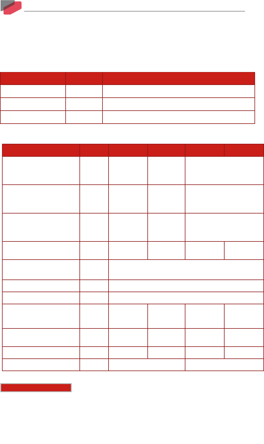
4.1. Physical Specifications
Feature Units All Types
Weight g (oz) 3.25 Kg (114.64 oz)
Dimension mm (in) 241 x 86.1 x 180.1 (9.45" x 3.39" x 7.09")
Mounting method Wall Mounted
4.2. Technical Data
Feature Units 30/230 40/230 30/480 40/480
Minimum supply voltage VAC
DC-500 Hz
1 x 60
or
3 x 60
3 x 60 3 x 140
Nominal supply voltage VAC
DC-500 Hz
1 x 230
or
3 x 230
3 x 230 3 x 400
3x 480
Maximum supply voltage VAC
DC-500 Hz
1 x 270
or
3 x 270
3 x 270 3 x 528
Maximum continuous power
output
kW 9.5 13 18.5 25
Efficiency at rated power (at
nominal conditions)
% > 98
Auxiliary supply voltage option VDC 18 to 30 VDC
Auxiliary power supply
VA 7
Continuous current limit (Ic)
Amplitude sinusoidal/DC
trapezoidal commutation
A 30 40 30 40
Continuous RMS sinusoidal
commutation current limit (Ic)
A 21 28 21 28
Peak Current A 60 80 60 80
Built In Shunt (peak Power) kW 5.9 11
Note on current ratings: The current ratings of the Gold Tuba are given in units of DC
amperes (ratings that are used for trapezoidal commutation or DC motors). The RMS (sinusoidal
commutation) value is the DC value divided by 1.41.