SimplIQ for Steppers Getting Started & Tuning and Commissioning Guide Ver 1.
The SimplIQ for Steppers Getting Started & Tuning and Commissioning Guide MAN-BELGS (Ver. 1.1) 2 Notice This guide is delivered subject to the following conditions and restrictions: This guide contains proprietary information belonging to Elmo Motion Control Ltd. Such information is supplied solely for the purpose of assisting users of the Bell servo drive in its installation. The text and graphics included in this manual are for the purpose of illustration and reference only.
The SimplIQ for Steppers Getting Started & Tuning and Commissioning Guide MAN-BELGS (Ver. 1.1) 3 Contents Chapter 1:Introduction............................................................................................................... 5 1.1 Qualified Personnel .................................................................................................... 7 1.2 Working with this Document ....................................................................................
The SimplIQ for Steppers Getting Started & Tuning and Commissioning Guide MAN-BELGS (Ver. 1.1) 4 Chapter 4:Advanced Control Tuning..................................................................................... 52 4.1 Start Step Control...................................................................................................... 52 4.2 Identification ............................................................................................................. 52 4.2.1 4.2.2 4.2.3 4.2.
The SimplIQ for Steppers Getting Started & Tuning and Commissioning Guide MAN-BELGS (Ver. 1.1) Chapter 1: Introduction The SimplIQ documentation and support software is divided into the following areas: Usage Phase Document Tool Exploratory Sales documents for SimplIQ and Bell Planning/configuration SimplIQ for Steppers Sizer configuration tool Decision/ordering Elmo Catalog and website Installation/assembly Device specific installation guide, e.g.
The SimplIQ for Steppers Getting Started & Tuning and Commissioning Guide MAN-BELGS (Ver. 1.1) The SimplIQ for Steppers Command Reference and the SimplIQ for Steppers Application Note, which describe in detail each software command used to manipulate the Bell motion controller. The SimplIQ Programming and Language Manual, which includes explanations of all the software tools that are part of Elmo’s Composer software environment.
The SimplIQ for Steppers Getting Started & Tuning and Commissioning Guide MAN-BELGS (Ver. 1.1) Caution (With or without a warning triangle, according to severity): This symbol indicates that minor personal injury or property damage may result if proper precautions are not taken. Note: This symbol highlights supplementary information This symbol indicates that the topic is normally handled automatically by support software, and the material is only given for enhanced understanding. 1.
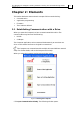
The SimplIQ for Steppers Getting Started & Tuning and Commissioning Guide MAN-BELGS (Ver. 1.1) Chapter 2: Elements This section deals with the most basic concepts of drive commissioning: Communication Application programming Firmware The Conductor Wizard 2.1 Establishing Communication with a Drive When you open the Composer it tries to communicate with the drive.
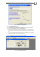
The SimplIQ for Steppers Getting Started & Tuning and Commissioning Guide MAN-BELGS (Ver. 1.1) Figure 2: Composer connecting window Ignore the Application Name field. Look at Last Successful Communication Properties. If the properties listed there are as required, click Finish. Otherwise, click Properties: For RS-232 you need to set the number of the COM port in use, the baud rate and the parity. The communication is always 8 bits in a byte, and it has one stop bit.
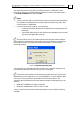
The SimplIQ for Steppers Getting Started & Tuning and Commissioning Guide MAN-BELGS (Ver. 1.1) The Smart Terminal lets you enter commands manually – please refer to the SimplIQ for Steppers Command Reference Manual. To send a command, type it in the Enter Command field and click Send. Notes: At the connection step you need to know the drive communication parameters. It is possible to change the drive communication parameters only later, after communication is established.
The SimplIQ for Steppers Getting Started & Tuning and Commissioning Guide MAN-BELGS (Ver. 1.1) Figure 5: Boot software message Click Yes to open the windows related to downloading the firmware. 2.1.1 Changing the Communication Parameters 2.1.1.1 Changing the RS-232 Communication Rate and Parity First set the desired parameters in the Composer smart terminal: PP[2] RS-232 baud rate. 5: 115,200; 4: 57,600 3: 38,400 2: 19,200 1: 9,600 0: 4,800 PP[4] RS-232 parity.
The SimplIQ for Steppers Getting Started & Tuning and Commissioning Guide MAN-BELGS (Ver. 1.1) Figure 7: The Connect button, circled in red Next select the new baud rate using the Properties button (See Figure 2). When the Composer Smart Terminal re-opens, you may use the SV command to make the new baud setting permanent. 2.1.1.2 Changing the CAN Communication Rate and ID First set the desired parameters in the Composer smart terminal: Parameter Description Range PP[13] CANopen device ID.
The SimplIQ for Steppers Getting Started & Tuning and Commissioning Guide MAN-BELGS (Ver. 1.1) Figure 9: The Connect button, circled in red Next select the new baud-rate using the Properties button (see Figure 2). When the Composer Smart Terminal re-opens, you may use the SV command to make the new baud setting permanent. 2.2 Application Parameters and Programming When you commission a drive, you create an Application. An Application refers to the entire data set you download and store into the drive.
The SimplIQ for Steppers Getting Started & Tuning and Commissioning Guide MAN-BELGS (Ver. 1.1) Use the LD command to copy the entire Serial Flash contents into the RAM. When you want to synchronize the Table Flash and the Serial Flash, use the SI=1 command. Notes: The SV, LD, and SI commands work on an entire data set. There is no way to save some of the parameters and not save others. SV does not automatically synchronize the Table Flash because Table Flash synchronizations take a long time.
The SimplIQ for Steppers Getting Started & Tuning and Commissioning Guide MAN-BELGS (Ver. 1.1) Figure 11: Open Application window Upon selection, look at the Communication Info data box. Verify that the communication parameters there are correct, or click Change to edit them. Then click Download to complete the downloading.
The SimplIQ for Steppers Getting Started & Tuning and Commissioning Guide MAN-BELGS (Ver. 1.1) 2.3.2 Normal Firmware Download In the Composer Smart Terminal, select Tools>Firmware Download. The following window opens: Figure 12: Download firmware window Use the Browse button to select the firmware .abs file, and then click OK.
The SimplIQ for Steppers Getting Started & Tuning and Commissioning Guide MAN-BELGS (Ver. 1.1) Figure 14: Firmware message 2.4 The Conductor Wizard 2.4.1 The Conductor Tabs The Conductor is the main tool for tuning the SimplIQ control functions. Figure 15: The Conductor window The Conductor manages some experiments for the tuning current and motion controls. You have a lot of flexibility in managing the experiment, but you do not need to be an expert.
The SimplIQ for Steppers Getting Started & Tuning and Commissioning Guide MAN-BELGS (Ver. 1.1) Figure 16: User editable fields in a tuning experiment 2.4.2 The Expert List The Expert list is a tool for observing and editing the drive parameters. It gives extra flexibility for the experienced user, and it lets you track which drive parameters you changed and how. Expert lists and the Conductor wizards work with the parameters in RAM only.
The SimplIQ for Steppers Getting Started & Tuning and Commissioning Guide MAN-BELGS (Ver. 1.1) Figure 17: Expert list window Here you see, and may edit (simply by clicking the value), each of the parameters that this wizard pad controls. The Expert List finds which parameters relate to a given Conductor tab using a keyword; Conductor tabs use keywords that are delimited by $ signs at both ends. You can, however, select another keyword from the list, or type a keyword manually. Then click Search .
The SimplIQ for Steppers Getting Started & Tuning and Commissioning Guide MAN-BELGS (Ver. 1.1) 2.4.3 Accepting a Change of Parameters When you change drive parameters with the Conductor, and you exit a tab, the conductor displays an exit comparison, as in Figure 18. After confirmation, the parameters are accepted and cannot be restored by the Conductor. Expert lists and the Conductor wizards work with the parameters in RAM only.
The SimplIQ for Steppers Getting Started & Tuning and Commissioning Guide MAN-BELGS (Ver. 1.1) Chapter 3: Getting Started with Sensors and Motion Control Setup 3.1 Introduction Tuning a SimplIQ drive to a motor is an ordered, step-by-step process. In this "Getting Started" chapter, we go through the setup process step by step. Note that this chapter does not contain all the detailed information for all product types and cannot take into account every possible aspect of the drive setup. 3.1.
The SimplIQ for Steppers Getting Started & Tuning and Commissioning Guide MAN-BELGS (Ver. 1.1) For this purpose, use the Input Logic tab in the Smart Terminal. Figure 19: Defining input logic For a detailed description of the functions that may be assigned to digital inputs, refer to the IL[N] command in the SimplIQ for Steppers Command Reference Manual. Correct digital input definitions help to guarantee that the drive generates only safe motions in the course of the tuning process.
The SimplIQ for Steppers Getting Started & Tuning and Commissioning Guide MAN-BELGS (Ver. 1.1) Do not specify brake delays greater than you actually need. Next, define the digital output for use as brake control; use the Output Logic tab of the Composer's Smart Terminal. For a detailed description of the functions that may be assigned to digital outputs, refer to the OL[N] command in the SimplIQ for Steppers Command Reference Manual.
The SimplIQ for Steppers Getting Started & Tuning and Commissioning Guide MAN-BELGS (Ver. 1.1) Notes: The MC command returns the current limit of the drive peak. You may set the current limits in the Conductor wizard as well. Refer to the CL[1],PL[1], and PL[2] commands in the SimplIQ for Steppers Command Reference Manual. 3.2.2.
The SimplIQ for Steppers Getting Started & Tuning and Commissioning Guide MAN-BELGS (Ver. 1.1) Figure 24: Position command limits Notes: This tab does not set the counting range (modulo limits). You can define the modulo limits in the setup window of the feedback sensor in the Conductor Wizard. In an open loop stepping application the relevant modulo limits are XM[1],XM[2]. The command limits must always be stricter than the feedback limit.
The SimplIQ for Steppers Getting Started & Tuning and Commissioning Guide MAN-BELGS (Ver. 1.1) 3.3.1 Setting up Sensor #1 Skip this section for open loop stepper applications. Figure 26: Sensor #1 tuning window Select the type of motion sensor #1. For a detailed explanation of each of the fields in the tab, click the Help button.
The SimplIQ for Steppers Getting Started & Tuning and Commissioning Guide MAN-BELGS (Ver. 1.1) Figure 27: Sensor #2 setup Sensor #2 can also be configured as a PWM input, or as a PWM output – refer to the online help. 3.4 Tuning the Drive to the Motor The next step is to define the motor type. After this step, the digital current control of the motor will work, at least at the basic level. The motor tuning will not be complete after this stage.
The SimplIQ for Steppers Getting Started & Tuning and Commissioning Guide MAN-BELGS (Ver. 1.1) 3.4.1 Selecting the Motor Type The SimplIQ drive can drive DC, 2-phase steppers, or brushless motors. Notes: Check that the motor leads are connected correctly. DC motors connect between M1 and M2. Brushless 3-phase motors connect between M1, M2, and M3, the phase order does not matter. Steppers connect one phase between M1 and M2, and the other phase between M3 and M4.
The SimplIQ for Steppers Getting Started & Tuning and Commissioning Guide MAN-BELGS (Ver. 1.1) 3.4.2 Tuning or Checking the Current Control In the same window, select the automatic current control tool. Figure 29: Entering the current control tuner The following window opens: Figure 30: Current tuning window In general, you do not have to change anything in this window, just click Start. When tuning is over, you will see a graph of the resulting current controller response.
The SimplIQ for Steppers Getting Started & Tuning and Commissioning Guide MAN-BELGS (Ver. 1.1) By clicking the frequency graph button, you can also see the frequency response of both the open and closed current controller. Notes: Setting greater phase margins reduces overshoot, but it also reduces the bandwidth of the resulting current loop. Apply the low-pass filter only if the current control is very noisy (this is very rare).
The SimplIQ for Steppers Getting Started & Tuning and Commissioning Guide MAN-BELGS (Ver. 1.1) Figure 31: The Commutation tab After checking if Digital Hall sensors are installed, go to the tuning process. The Conductor is responsible to make the motor rotate, so that when the direction is positive: The position sensor reading will increase. The consumed current will be positive.
The SimplIQ for Steppers Getting Started & Tuning and Commissioning Guide MAN-BELGS (Ver. 1.1) Check Reset Commutation Every Hall Edge if your position sensor is not mounted directly on the motor, but through a gear train or a backlash. 3.6 Motion Tuning This step depends upon the drive method you choose. 3.6.1 Torque Drive If you want to enhance the torque control smoothness and performance, you may want cogging and speed corrections.
The SimplIQ for Steppers Getting Started & Tuning and Commissioning Guide MAN-BELGS (Ver. 1.1) 3.6.2 Stepper Drives with no Commutation Sensor For stepper drives, click the Motion tab and select either Open loop stepper or Closed loop stepper with sensor #1. Figure 34: Motion tab Here you need to enter the holding torque component (static torque, speed dependent torque, and accelerating torque). The Motor Calculator button helps you to find the required parameters.
The SimplIQ for Steppers Getting Started & Tuning and Commissioning Guide MAN-BELGS (Ver. 1.
The SimplIQ for Steppers Getting Started & Tuning and Commissioning Guide MAN-BELGS (Ver. 1.1) Figure 36: Motor calculation window Complete the Inputs section of the form from the motor datasheet; then click Calculate. This will give the holding torque fixed, speed dependent, and acceleration dependent components, and also the maximum deceleration SD – for further explanations click the Help button. For closed loop position control, this calculator also obtains the dynamic torque limit PF[29].
The SimplIQ for Steppers Getting Started & Tuning and Commissioning Guide MAN-BELGS (Ver. 1.1) Figure 37: Motion tab for closed loop control The Conductor presents an advanced set of motion tuning tools. The usage level for the tools can be anything from novice to control expert. Before using the Motion tab read the following sections. The process is divided into several steps: Prepare for identification. Identification. Design. Verification.
The SimplIQ for Steppers Getting Started & Tuning and Commissioning Guide MAN-BELGS (Ver. 1.1) Notes: This step assumes that you have properly set the current control and the commutation in advance. If the current control or commutation are not optimum, the controller tuning will yield poor results. If you use analog sensors (Analog encoder, Resolver, Potentiometer, LVDT, etc.) take extra care to ensure your position signals are clean before you start motion.
The SimplIQ for Steppers Getting Started & Tuning and Commissioning Guide MAN-BELGS (Ver. 1.1) Figure 38: Start step designer window Click Start and wait for the Conductor. Usually it succeeds and you have completed the process. If it failed, use the controls and read the online help in order to obtain a working starting controller. The starting controller replaces the motion controller with a lowperformance fixed controller.
The SimplIQ for Steppers Getting Started & Tuning and Commissioning Guide MAN-BELGS (Ver. 1.1) The method for finding the transfer function is simple: inject sine signals of varying frequency to the plant and measure the resulting motion. The implementation of this method by the Conductor, however, is quite complex. The transfer function of motion systems depends on the signal amplitude and the working conditions.
The SimplIQ for Steppers Getting Started & Tuning and Commissioning Guide MAN-BELGS (Ver. 1.1) Figure 40: Example of a frequency response Click OK to return to the main identification screen, then save your work using the File>Save menu. Name it MyFirstIden.idn. 3.6.3.3 Design With the identification results you can design a controller. The controller has to meet the following goals: The robustness figures of merit: acceptable gain and phase margins.
The SimplIQ for Steppers Getting Started & Tuning and Commissioning Guide MAN-BELGS (Ver. 1.1) Figure 41: Add identified plant to the designer Select Tools>Automatic design.
The SimplIQ for Steppers Getting Started & Tuning and Commissioning Guide MAN-BELGS (Ver. 1.1) Figure 42: Automatic design window Click Run.
The SimplIQ for Steppers Getting Started & Tuning and Commissioning Guide MAN-BELGS (Ver. 1.1) You have now completed your first successful design. You can save it to a file. Select Tools>Download Design, and in the following window: select the “Position” unit mode. 3.6.3.4 Verification In the verification stage simply run step responses and judge them according to your needs. Click the Verification tool.
The SimplIQ for Steppers Getting Started & Tuning and Commissioning Guide MAN-BELGS (Ver. 1.
The SimplIQ for Steppers Getting Started & Tuning and Commissioning Guide MAN-BELGS (Ver. 1.1) Figure 45: Controller verification results 3.7 Fine Tuning The Fine Tuning tab enables special enhancements to be tuned. This is not required for all applications. The following fine tunings are available: Cogging compensation Analog encoder index tuning 3.7.1 Cogging Compensation The first compensation is for cogging. It becomes available when you check Enable Cogging Compensation.
The SimplIQ for Steppers Getting Started & Tuning and Commissioning Guide MAN-BELGS (Ver. 1.
The SimplIQ for Steppers Getting Started & Tuning and Commissioning Guide MAN-BELGS (Ver. 1.1) Figure 47: Cogging compensation tuner window The following options are available: Set the cogging compensation to default, i.e., there will be no cogging compensation. Load a cogging table from a file, without measuring anything. Measure the actual motor cogging by clicking Start.
The SimplIQ for Steppers Getting Started & Tuning and Commissioning Guide MAN-BELGS (Ver. 1.
The SimplIQ for Steppers Getting Started & Tuning and Commissioning Guide MAN-BELGS (Ver. 1.1) 3.7.2 Fine Tuning an Analog Encoder If sensor #1 is set to "Analog incremental encoder" in the "Sensor #1" window, then the "Analog index tuning" button is visible. This tuning defines the signal level and position where analog index capture occurs. Please note that for analog encoder, the index appears at different positions for forward travel and for reverse travel; both cases are measured.
The SimplIQ for Steppers Getting Started & Tuning and Commissioning Guide MAN-BELGS (Ver. 1.1) Figure 49: Analog index tuning After you set the parameters for the experiment, click Start to begin; progress is displayed in the progress bar at the bottom of the window.
The SimplIQ for Steppers Getting Started & Tuning and Commissioning Guide MAN-BELGS (Ver. 1.1) 3.8 Database Maintenance Finally, save the results. Click the Database tab: Figure 50: Database maintenance tab Check the database integrity. This checks for certain conflicts that can prevent the motor from starting. For example, if you selected a commutation finding method by CA[17] that does not match the installed sensors, the motor will not start and it will report "Bad Database".
The SimplIQ for Steppers Getting Started & Tuning and Commissioning Guide MAN-BELGS (Ver. 1.1) Chapter 4: Advanced Control Tuning This chapter is intended for users wishing to use the extra flexibility of the motion control tuning system beyond the "getting started" level. This chapter assumes you are familiar with Section 3.6.3. Feedback design is a four-step procedure. The first step is to generate a low performance controller that is called the "starting step controller".
The SimplIQ for Steppers Getting Started & Tuning and Commissioning Guide MAN-BELGS (Ver. 1.1) 4.2.1 Identification and Uncertainty The identification produces a frequency response. A frequency response is a characteristic of a linear, time invariant plant. We take frequency response not because the plant is really linear and time invariant; but because all the established control design theory deals with plants having frequency responses.
The SimplIQ for Steppers Getting Started & Tuning and Commissioning Guide MAN-BELGS (Ver. 1.1) Open Save New Cleanup Figure 51: Identification file maintenance options You can reset the identification process (New) and store results (Save). You can also edit existing identification results. You can add frequency points to an existing identification. Open an existing file, then add the frequencies you want (further details appear later in this manual).
The SimplIQ for Steppers Getting Started & Tuning and Commissioning Guide MAN-BELGS (Ver. 1.1) Free: For non-restricted displacement around the initial position. The starting step controller will keep the motor with constant speed, so that the frictions will minimally affect identification. This mode gives the best linear identification. Bounded: For restricted displacement around the initial position with given position limits around the initial position.
The SimplIQ for Steppers Getting Started & Tuning and Commissioning Guide MAN-BELGS (Ver. 1.1) Although the automated frequency search works well in most cases, the Conductor may miss very narrow resonance/anti-resonance pairs. We recommend that you first let the Conductor identify with automated frequency search. Check Automatic Refinement to allow intensified resolution where the frequency response changes rapidly, e.g. near resonant modes.
The SimplIQ for Steppers Getting Started & Tuning and Commissioning Guide MAN-BELGS (Ver. 1.1) Figure 54: Frequency Editor, when no identification is available The red points, and the list in the Frequency area, show the frequencies for plant excitation. For every frequency there is also an associated excitement current amplitude. Before the identification you can see the default set of frequencies that the Conductor sets before learning the plant.
The SimplIQ for Steppers Getting Started & Tuning and Commissioning Guide MAN-BELGS (Ver. 1.1) Figure 55: Frequency editor window after identification The blue points show identification results. There are no red points and no point listing in the selection box since all the frequency points have been run and there has not yet been a new request. You can add and edit new frequency points and run them; their identification result will be appended to the existing frequency response results.
The SimplIQ for Steppers Getting Started & Tuning and Commissioning Guide MAN-BELGS (Ver. 1.
The SimplIQ for Steppers Getting Started & Tuning and Commissioning Guide MAN-BELGS (Ver. 1.1) Appendix A: Manual Tuning of Speed and Position Control A.1 Scope This Appendix explains how to manually tune controllers of the following types: 1. A PI speed controller. 2. Cascaded position controller: The inner loop is a PI speed controller and the outer loop is a position simple gain controller. 3. A PI speed controller with a single notch filter, a low-pass filter or both. 4.
The SimplIQ for Steppers Getting Started & Tuning and Commissioning Guide MAN-BELGS (Ver. 1.1) 1 Treat unbalanced systems with extreme care. A.3 Make it Simple This Appendix gives some simple guidelines for manual controller tuning. In order to simplify the tuning process we divide it into a series of steps. The rules of simplification are: 1 2 Never tune your controller to perform better than you need. A controller of lower bandwidth decreases stresses and is more robust to changes and ageing.
The SimplIQ for Steppers Getting Started & Tuning and Commissioning Guide MAN-BELGS (Ver. 1.1) A.4 Keep Margins It is very tempting to increase the controller gains and enjoy the maximal performance of your system. You must bear in mind that the price of maximum performance is decreased robustness to system variations. The higher the gains, the greater the chance that the system will become noisy or even unstable due to changing work conditions, or due to ageing.
The SimplIQ for Steppers Getting Started & Tuning and Commissioning Guide MAN-BELGS (Ver. 1.1) Manual gain scheduling: The controller parameters may adapt due to a user program or an external command. For example, the controller gains of a winder may be increased as it rolls and gains weight. For convenience, when you program a fixed controller you don't overwrite the schedulable parameters, and vice versa. The Auto-tuner always programs an automatically gain-scheduled controller. A.5.
The SimplIQ for Steppers Getting Started & Tuning and Commissioning Guide MAN-BELGS (Ver. 1.1) A.5.4 Evaluating a Step Response – Rise Time, Settling Time, and Overshoot. A step response is the waveform (position or speed) the motor exhibits when its reference command (position or speed) changes abruptly. Step responses are not very practical in real-life motoring applications, as the reference commands are nearly always acceleration limited and many times smoothed.
The SimplIQ for Steppers Getting Started & Tuning and Commissioning Guide MAN-BELGS (Ver. 1.1) 16000 14000 Step response 12000 10000 8000 AAcceptable cceptablemargins: margins: Nice response good response Too low too margins: large overshoot oscillations Margins low: large overshoot and and oscillations Too much settling Margins toomargins: high: longlong settling time time Reference Reference 6000 4000 2000 0 0 0.01 0.02 0.03 0.04 0.05 0.06 0.07 0.08 Tim e (sec.
The SimplIQ for Steppers Getting Started & Tuning and Commissioning Guide MAN-BELGS (Ver. 1.1) A.7 Testing the Response of a Controller Manual tuning is an iterative process in which you select parameters for the controller, and then test them. A.7.1 Current Limits Beware that the peak current limit and the continuous current limit of the drive may differ. If you use excessive current levels in the experiment, the drive may switch automatically to the continuous limit, and exhibit saturation behavior. A.
The SimplIQ for Steppers Getting Started & Tuning and Commissioning Guide MAN-BELGS (Ver. 1.1) A.8 Fixed Gain Manual Tuning for a Speed Loop This section deals with choosing the KI and KP parameters of the PI controller and the parameters of the High order filter. We first describe how to select the KI and KP parameters. Then we explain how to add a low-pass filter. Finally we explain how to decide if a notch filter is needed and how to add it. A.8.
The SimplIQ for Steppers Getting Started & Tuning and Commissioning Guide 68 MAN-BELGS (Ver. 1.1) Figure 59 reveals the following: 1. The measured output does not reach the commanded step. 2. Current command is far from saturation, therefore you can increase the velocity command. Counts/sec. Figure 60 repeats the same test with increased velocity and test duration as given in the table below. Note that there is a long time duration (from 0.7 to 1.3 sec.
The SimplIQ for Steppers Getting Started & Tuning and Commissioning Guide Counts/sec. MAN-BELGS (Ver. 1.1) 1.5 0.9 x 10 0.3 -0.3 -0.9 -1.5 0.1 4 KI=120,KP=40 KI=90,KP =30 KI=60,KP =20 KI=30,KP =10 Reference 0.12 Am pere 1.5 1.1 0.7 0.14 0.16 Tim e (sec.) 0.18 0.2 0.14 0.16 Tim e (sec.) 0.18 0.2 KI=120,KP=40 KI=90,KP =30 KI=60,KP =20 KI=30,KP =10 0.3 -0.1 -0.5 0.1 0.12 Figure 61: Test results for maximum KP for KI/KP=3 Adjust the speed command for optimal tuning.
The SimplIQ for Steppers Getting Started & Tuning and Commissioning Guide MAN-BELGS (Ver. 1.1) Counts/sec. KP 30 2.5 1.7 KI Marked On Plot x 10 0.9 0.1 -0.7 -1.5 0.1 Velocity 12000 Am pere 0.3 -0.1 -0.5 0.1 -Displ. 5000 Rec. T. 0.48 sec Rec. Res 400 musec Profile off 4 KI=8000 KI=6000 KI=4000 KI=2000 KI=1000 KI=500 Reference 0.12 1.5 1.1 0.7 +Displ. 5000 0.14 0.16 Tim e (sec.) 0.18 0.2 0.14 0.16 Tim e (sec.) 0.18 0.2 KI=8000 KI=6000 KI=4000 KI=2000 KI=1000 KI=500 0.
The SimplIQ for Steppers Getting Started & Tuning and Commissioning Guide Counts/sec. MAN-BELGS (Ver. 1.1) 3 2.1 x 10 4 KI=20000,KP =30 KI=16000,KP =30 Reference 1.2 0.3 -0.6 -1.5 0.1 0.12 Am pere 2 0.14 0.16 Tim e (sec.) 0.18 0.2 0.14 0.16 Tim e (sec.) 0.18 0.2 KI=20000,KP =30 KI=16000,KP =30 1.2 0.4 -0.4 -1.2 -2 0.1 0.12 Figure 63: An example of unacceptable controller – KI is too large C ounts/sec.
The SimplIQ for Steppers Getting Started & Tuning and Commissioning Guide MAN-BELGS (Ver. 1.1) Theoretical Tip: We suggest to start the manual tuning with KI/KP= 6π , assuming you can achieve a bandwidth greater than 3 Hz. Then find the maximum KP where KI/KP=3. Above the bandwidth of 3 Hz, the value of KP will be responsible for stability rather than KI. The next step is to decrease KP by about 30% to leave space for increasing KI and leave it fixed while increasing KI.
The SimplIQ for Steppers Getting Started & Tuning and Commissioning Guide Counts/sec. MAN-BELGS (Ver. 1.1) 2 1.3 x 10 4 KI=150,KP =50 KI=120,KP =40 Reference 0.6 -0.1 -0.8 -1.5 0.1 0.12 Am pere 2 0.14 0.16 Tim e (sec.) 0.18 0.2 0.14 0.16 Tim e (sec.) 0.18 0.2 KI=150,KP =50 KI=120,KP =40 1.4 0.8 0.2 -0.4 -1 0.1 0.12 Counts/sec. Figure 65: Tests for finding the maximum KP for KI/KP=3. KP=40 is acceptable, while KP=50 is too large 2.5 1.7 x 10 0.9 0.1 -0.7 -1.5 0.
The SimplIQ for Steppers Getting Started & Tuning and Commissioning Guide MAN-BELGS (Ver. 1.1) If a settling time of 25 msec at least is satisfactory, try to insert a second order low-pass filter. The starting corner frequency is (10/Settling time) Hz. Iterate step 2 for low-pass filters decreasing by 25% each test. Repeat, decreasing the lowpass frequency until a satisfactory controller is achieved; see Guideline 4 below.
The SimplIQ for Steppers Getting Started & Tuning and Commissioning Guide MAN-BELGS (Ver. 1.1) 0.4 Am pere 0.36 0.32 0.28 0.24 0.2 0.3 0.32 0.34 0.36 Tim e (sec.) 0.38 0.4 Figure 68: Zoom of current test measurement for measuring the plant’s expected resonance. (RSpeed2) Add a notch at frequency 359 Hz with damping factor of 0.07. Click the Highorder Filter Design button, choose a notch filter, type its corner frequency and use the slider to choose the damping factor.
The SimplIQ for Steppers Getting Started & Tuning and Commissioning Guide MAN-BELGS (Ver. 1.1) Counts/sec. Figure 69: Notch filter at the corner frequency 359 Hz and a damping factor of 0.07 3 1.8 x 10 4 0.6 -0.6 -1.8 -3 0 Speed Reference 0.1 0.2 0.3 Tim e (sec.) 0.4 0.5 0.1 0.2 0.3 Tim e (sec.) 0.4 0.5 Am pere 2.4 1.76 1.12 0.48 -0.16 -0.
The SimplIQ for Steppers Getting Started & Tuning and Commissioning Guide MAN-BELGS (Ver. 1.1) 0.4 Am pere 0.36 0.32 0.28 0.24 0.2 0.3 0.32 0.34 0.36 Tim e (sec.) 0.38 0.4 Figure 71: Zoom of current test measurement for the same controller used for Figure 68 with Notch Remark: Figure 71 reveals two remaining oscillations, one about 75 Hz and the other 860 Hz. The oscillation at 75 Hz is due to cogging and not due to a mechanical resonance.
The SimplIQ for Steppers Getting Started & Tuning and Commissioning Guide MAN-BELGS (Ver. 1.1) A.9 Executing Manual Tuning for a Cascaded Position Controller Design of a position controller is a two-stage sequence. The first is to tune a speed controller and the second is to tune the simple gain outer controller. Assume the speed controller was designed and tested as shown in Figure 62 for which KI=8000, KP=30. The rise time is dT=0.0034 seconds. The suggested dual loop controller is: 1.
The SimplIQ for Steppers Getting Started & Tuning and Commissioning Guide MAN-BELGS (Ver. 1.1) Counts 2500 2000 1500 1000 500 0 0 Speed Reference 0.02 0.04 0.06 Tim e (sec.) 0.08 0.1 0.02 0.04 0.06 Tim e (sec.) 0.08 0.1 Am pere 4 2.8 1.6 0.4 -0.8 -2 0 Figure 72: Tests of position design 3. The third step is to iterate on the KI parameter of the inner loop and on the outer loop KP parameter.
The SimplIQ for Steppers Getting Started & Tuning and Commissioning Guide MAN-BELGS (Ver. 1.1) For manual gain scheduling, tune a series of fixed controllers and log their parameters. Keep in mind that the High-order filter must be similar for all the parameter sets. Then program them to the controllers’ array using the KG[N] command, and set GS[2] for the selection of the appropriate controller. Refer to the chapter on the Speed and the Position Controller in the Application Manual for more details. A.
The SimplIQ for Steppers Getting Started & Tuning and Commissioning Guide MAN-BELGS (Ver. 1.1) 12000 10000 c ounts/sec 8000 6000 4000 2000 0 0 10 20 30 40 50 60 70 Index Figure 73: An example of option speeds Position gain scheduling is similar to speed gain scheduling. The minimal recommended position settling time = twice the speed settling time.
The SimplIQ for Steppers Getting Started & Tuning and Commissioning Guide MAN-BELGS (Ver. 1.1) Appendix B: A Short Course in Linear Control This section goes over some theoretical matters that are the essence of the Conductor. It brings continuous time theory although the SimplIQ is a sampled, discrete system. This simplifies the theoretical presentation while maintaining physical understanding. B.1 Linear Systems and Transfer Functions A system is something that has inputs and outputs.
The SimplIQ for Steppers Getting Started & Tuning and Commissioning Guide MAN-BELGS (Ver. 1.1) B.2 Mathematical Models for LTI Systems LTI systems, like any other system, are modeled by differential or algebraic equations.
The SimplIQ for Steppers Getting Started & Tuning and Commissioning Guide MAN-BELGS (Ver. 1.1) Comparing (6) and (2), we find that the Laplace variable s is equivalent to the t 1 d ⇔ ∫ dτ s⇔ s .
The SimplIQ for Steppers Getting Started & Tuning and Commissioning Guide MAN-BELGS (Ver. 1.1) 30 ω=1.5 ω=2 20 L(jω) 10 ω=3 ω=5 ω=10 0 ω=20 B d -10 ω=40 -20 ω=60 -30 ω=80 -40 -360 -315 -270 -225 -180 deg -135 -90 -45 0 Figure 76: An example Nichols chart B.3 Motor Systems Models B.3.1 A Simple Model A motor is a device that translates electrical energy into mechanical energy. Figure 77 is a simplified schematic representation of a fixed magnet electrical motor.
The SimplIQ for Steppers Getting Started & Tuning and Commissioning Guide MAN-BELGS (Ver. 1.1) v + i 1 R _ KT T ⋅ 1 J − Ls 1 s θ −B KE Figure 78: Block diagram of the simplified DC motor model The transfer function from voltage input, v , to motor shaft angle, θ , is 1 / KE θ& L JR = , τe = ; τm = 2 R KT K E v s (1 + sτ m + τ e τ m s ) (8) Usually, τ e is much smaller then τ m .
The SimplIQ for Steppers Getting Started & Tuning and Commissioning Guide MAN-BELGS (Ver. 1.1) Suppose that in the system of Figure 79 the motor is brought abruptly to some constant torque. Initially the load will not react. This is because the axis must be deformed in order to convey torque to the load. When the load finally moves, its acceleration will oscillate. The oscillations in the load will induce oscillations in the motor, as shown in Figure 80 for a step command.
The SimplIQ for Steppers Getting Started & Tuning and Commissioning Guide MAN-BELGS (Ver. 1.
The SimplIQ for Steppers Getting Started & Tuning and Commissioning Guide MAN-BELGS (Ver. 1.1) -20 -30 -40 B -50 d -60 -70 3 4 5 6 7 8 9 10 -40 -60 -80 -100 g -120 e d -140 -160 -180 3 4 5 6 7 8 9 10 ω 15 20 30 20 30 Figure 82: Bode plot of a motor with flexible load (resonance model) At low frequencies, well below the oscillations, the transfer function rolls down with a fixed slope and fixed phase angle.
The SimplIQ for Steppers Getting Started & Tuning and Commissioning Guide MAN-BELGS (Ver. 1.1) B.4 Feedback Control The system we consider here is shown in block diagram form in Figure 84, where P denotes the controlled transfer function (the plant).
The SimplIQ for Steppers Getting Started & Tuning and Commissioning Guide MAN-BELGS (Ver. 1.1) The sensor, which measures the plant output, adds noise to the measurement. The controller amplifies the measurement noise. A highly amplified measurement noise may even saturate the plant input, which might destabilize the system, or produce an unacceptable output. Feedback should be carefully designed in order to avoid loss of stability due to plant uncertainty and plant input saturation. B.4.
The SimplIQ for Steppers Getting Started & Tuning and Commissioning Guide MAN-BELGS (Ver. 1.1) Phase margin – We will say that the phase margin of the transfer function L( s ) ο ο is ϕ (degree units), if ϕ is the smallest positive value such that at any ο frequency, ω PM , for which L( jω PM ) = 1 , the phase of L( jω PM ) is − 180 + ϕ . The third design criterion is the system’s bandwidth. The bandwidth is a figure of merit for the performance of the closed loop system during operation.
The SimplIQ for Steppers Getting Started & Tuning and Commissioning Guide MAN-BELGS (Ver. 1.1) PD controllers are not useful, as they permit steady state errors in the presence of friction and unbalance. In the presence of friction or unbalance the controller output u must be kept steadily non-zero while the tracking error vanished. A PD controller cannot do that.
The SimplIQ for Steppers Getting Started & Tuning and Commissioning Guide 94 MAN-BELGS (Ver. 1.1) For speed control, the derivative term represents acceleration. Acceleration is hard to estimate with acceptable noise, so that the inclusion of the D term in speed controllers is impractical. We therefore use the PI (PID without the D) form for speed controllers.