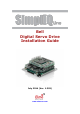
Bell Digital Servo Drive Installation Guide July 2014 (Ver. 1.302) www.elmomc.
Notice This guide is delivered subject to the following conditions and restrictions: • This guide contains proprietary information belonging to Elmo Motion Control Ltd. Such information is supplied solely for the purpose of assisting users of the Bell servo drive in its installation. • The text and graphics included in this manual are for the purpose of illustration and reference only. The specifications on which they are based are subject to change without notice.
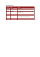
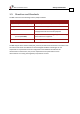
Revision History Version Date Details Ver. 1.0 Jan 2008 Initial release Ver. 1.1 June 2009 General update Ver. 1.2 Dec 2010 MTCR 12-001-10: Figure 3-1 and Section 4.2 removed from version 1.1. Ver. 1.3 July 2012 Template update Ver. 1.301 Feb 2013 Added a caution and recommendation on the type of cleaning solution to use for the Elmo unit. Ver. 1.
Elmo Worldwide Head Office Elmo Motion Control Ltd. 60 Amal St., P.O. Box 3078, Petach Tikva 49516 Israel Tel: +972 (3) 929-2300 • Fax: +972 (3) 929-2322 • info-il@elmomc.com North America Elmo Motion Control Inc. 42 Technology Way, Nashua, NH 03060 USA Tel: +1 (603) 821-9979 • Fax: +1 (603) 821-9943 • info-us@elmomc.com Europe Elmo Motion Control GmbH Hermann-Schwer-Strasse 3, 78048 VS-Villingen Germany Tel: +49 (0) 7721-944 7120 • Fax: +49 (0) 7721-944 7130 • info-de@elmomc.
Bell Installation Guide Safety Information MAN-BELIG Ver. 1.302 Table of Contents Chapter 1: 1.1. 1.2. 1.3. 1.4. 1.5. Warnings ........................................................................................................................ 8 Cautions .......................................................................................................................... 8 Directives and Standards ................................................................................................
Bell Installation Guide Safety Information MAN-BELIG Ver. 1.302 3.11. I/Os ............................................................................................................................... 35 3.11.1. Digital Input ................................................................................................... 35 3.11.2. Digital Output ................................................................................................ 37 3.11.3. Analog Input ..................................
Bell Installation Guide Safety Information MAN-BELIG Ver. 1.302 Chapter 1: Safety I nform ation In order to achieve the optimum, safe operation of the Bell stepper drive, it is imperative that you implement the safety procedures included in this installation guide. This information is provided to protect you and to keep your work area safe when operating the Bell and accompanying equipment. Please read this chapter carefully before the installation process.
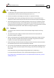
Bell Installation Guide Safety Information MAN-BELIG Ver. 1.302 1.1. Warnings • To avoid electric arcing and hazards to personnel and electrical contacts, never connect/disconnect the servo drive while the power source is on. • Disconnect the Bell from all voltage sources before it is opened for servicing. • The Bell stepper drive contains grounding conduits for electric current protection. Any disruption to these conduits may cause the instrument to become hot (live) and dangerous.
Safety Information Bell Installation Guide MAN-BELIG Ver. 1.302 1.3.
Bell Installation Guide Safety Information MAN-BELIG Ver. 1.302 1.4. CE Mark Conformance The Bell stepper drive is intended for incorporation in a machine or end product. The actual end product must at a minimum comply with all safety aspects of the relevant requirements of the European Safety of Machinery Directive 98/37/EC as amended, and with those of the most recent versions of standards EN60204-1 and EN292-2.
Bell Installation Guide 11 MAN-BELIG (Ver. 1.302) Chapter 2: I ntroduction This installation guide describes the Bell stepper drive and the steps for its wiring, installation and power-up. Following these guidelines ensures maximum functionality of the drive and the system to which it is connected. 2.1. Drive Description Elmo Motion Control’s Bell is an intelligent digital stepper drive designed to add stepper technology to the SimplIQ product family.
Introduction Bell Installation Guide MAN-BELIG (Ver. 1.302) 2.2.3. Feedback Options • Incremental Encoder - up to 40 Mega-Counts per second • Digital Halls - up to 2 kHz • Incremental Encoder with Digital Halls for commutation - up to 40 Mega-Counts • Interpolated Analog Sine/Cosine Encoder - up to 400 kHz Internal Interpolation - up to x4096 Automatic correction of amplitude mismatch, signal offset • Analog Halls • Auxiliary Encoder inputs (ECAM, follower, etc.
Introduction Bell Installation Guide MAN-BELIG (Ver. 1.302) 2.4. How to Use this Guide In order to install and operate your Bell stepper drive, you will use this manual in conjunction with a set of Elmo and Digital Feedback Technologies documentation.
Installation Bell Installation Guide MAN-BELIG (Ver. 1.302 Chapter 3: I nstallation 3.1. Site Requirements You can guarantee safe operation of the Bell by ensuring that it is installed in an appropriate environment. Environmental Condition Value Ambient operating temperature 0 °C to 40 °C (32 °F to 104 °F) Maximum relative humidity 90% non-condensing Operating area atmosphere No flammable gases or vapors permitted in area Models for extended environmental conditions are available.
Installation Bell Installation Guide MAN-BELIG (Ver. 1.302 The part number at the top gives the type designation as follows: The model that is currently available is the BEL-5/100. Verify that the Bell drive is the type that you ordered, and ensure that the voltage meets your specific requirements. 3.3. 3.3.1. No.
Installation Bell Installation Guide MAN-BELIG (Ver. 1.302 3.3.2.
Installation Bell Installation Guide MAN-BELIG (Ver. 1.302 3.3.3. Connector J2 Pin Signal Function J2/1 +5V Encoder/Hall +5 V supply voltage.
Installation Bell Installation Guide MAN-BELIG (Ver. 1.302 3.5. Integrating the Bell on a PCB The Bell is designed to be mounted on a PCB, either by soldering its pins directly to the PCB or by using suitable socket connectors. In both cases the following rules apply: 3.5.1. Traces 1. The size of the traces on the PCB (thickness and width) are determined by the current carrying capacity required by the application.
Installation Bell Installation Guide MAN-BELIG (Ver. 1.302 The returns above are all shorted within the Bell in a topology that results in optimum performance. 1. When wiring the traces of the above functions on the Integration Board the returns of each function must be wired separately to its designated terminal on the Bell. DO NOT USE A COMMON GROUND PLANE. Shorting the commons on the Integration Board may cause performance degradation (ground loops, etc.). 2.
Installation Bell Installation Guide MAN-BELIG (Ver. 1.302 3.6. The Bell Connection Diagram Figure 3: Bell Connection Diagram Table of Contents |www.elmomc.
Installation Bell Installation Guide MAN-BELIG (Ver. 1.302 3.7. Main Power and Motor Power Pin Function Cable Pin Positions VP+ Pos.
Installation Bell Installation Guide MAN-BELIG (Ver. 1.302 3.7.1. Connecting Motor Power Connect the M1, M2, M3, M4 and PE pins on the Bell in the manner described in Section 3.5 (Integrating the Bell on a PCB). The phase connection is arbitrary as the Composer will establish the proper commutation automatically during setup. However, if you plan to copy the setup to other drives, then the phase order on all copy drives must be the same. Note: The Bell is equipped with four motor wires.
Installation Bell Installation Guide MAN-BELIG (Ver. 1.302 3.7.2. Connecting Main Power Connect the VP+, PR and PE pins on the Bell in the manner described in Section 3.5 (Integrating the Bell on a PCB). The source of the 12 ~ 95 VDC Main Power Supply must be isolated. Figure 5: Main Power Supply Connection Diagram (no Auxiliary Supply) Table of Contents |www.elmomc.
Installation Bell Installation Guide MAN-BELIG (Ver. 1.302 3.8. Auxiliary Supply (for Drive Logic) Note: Notes for 12 ~ 95 VDC auxiliary supply connections: The source of the 12 ~ 95 VDC Auxiliary Supply must be isolated. Connect the VL and PR pins on the Bell in the manner described in Section 3.5 (Integrating the Bell on a PCB).
Installation Bell Installation Guide MAN-BELIG (Ver. 1.302 3.8.2. Separate Auxiliary Supply Power to the Auxiliary Supply can be provided by a separate Auxiliary Supply. Figure 7: Separate Auxiliary Supply Connection Diagram Table of Contents |www.elmomc.
Installation Bell Installation Guide MAN-BELIG (Ver. 1.302 3.8.3. Shared Supply A "Main" DC Power Supply can be designed to supply power to the drive's Logic as well as to the Main Power (see Figure 6). If backup functionality is required (for storing control parameters in case of power-outs) an additional backup supply can be connected by implementing 'diode coupling' (see the Aux. Backup Supply in Figure 8: Shared Supply Connection Diagram ).
Installation Bell Installation Guide MAN-BELIG (Ver. 1.302 3.9. Main Feedback The Main Feedback port is used to transfer feedback data from the motor to the drive. The Bell can accept any of the following devices as a main feedback mechanism: • Incremental encoder only. • Incremental encoder with digital hall sensors. • Digital hall sensors only. • Incremental Analog (Sine/Cosine) encoder (option).
Installation Bell Installation Guide MAN-BELIG (Ver. 1.302 Figure 9: Main Feedback - Incremental Encoder Connection Diagram Table of Contents |www.elmomc.
Installation Bell Installation Guide MAN-BELIG (Ver. 1.302 Figure 10: Main Feedback- Interpolated Analog Encoder Connection Diagram 3.10. Auxiliary Feedback For auxiliary feedback, select one of the following options: Single-ended auxiliary encoder input, for the input of position data of the master encoder in follower or ECAM mode. Pulse-and-direction input, for single-ended input of pulse-and-direction position commands.
Installation Bell Installation Guide MAN-BELIG (Ver. 1.302 Auxiliary Feedback Main Feedback YA[4] = 4 (Aux. Feedback: output) YA[4] = 2 (Aux. Feedback: input) YA[4] = 0 (Aux. Feedback: input) Any application where two feedbacks are used by the drive. Any application where two feedbacks are used by the drive. The Auxiliary Feedback port serves as an input for the auxiliary incremental encoder. The Auxiliary Feedback port serves as an input for Pulse & Direction Commands.
Installation Bell Installation Guide MAN-BELIG (Ver. 1.302 3.10.2. Pin Auxiliary Feedback: Single-Ended Encoder Input Option (YA[4]=2) Signal Function J1/4 SUPRET Supply return J1/19 INDEX Auxiliary index input J1/18 CHB Auxiliary channel B input J1/5 CHA Auxiliary channel A input Pin Position Note: The Bell’s Auxiliary Feedback is single-ended. When mounted on an integration board, circuitry can be added to make it differential.
Installation Bell Installation Guide MAN-BELIG (Ver. 1.302 Figure 12: Single-ended Auxiliary Encoder Input - Recommended Connection Diagram Figure 13: Differential Auxiliary Encoder Input – Highly Recommended Connection Diagram Table of Contents |www.elmomc.
Installation Bell Installation Guide MAN-BELIG (Ver. 1.302 3.10.3. Pin Auxiliary Feedback: Pulse-and-Direction Input Option (YA[4]=0) Signal Function Pin Position J1/4 SUPRET Supply return J1/18 DIR/CHB Direction input (push/pull 5 V or open collector) J1/5 PULS/CHA Pulse input (push/pull 5 V or open collector) Note: The Bell’s Auxiliary Feedback is single-ended. When mounted on an integration board circuitry can be added to make it differential.
Installation Bell Installation Guide MAN-BELIG (Ver. 1.302 Figure 15: Pulse-and-Direction Auxiliary Encoder Input – Buffered Connection Diagram Figure 16: Pulse-and-Direction Auxiliary Encoder Input – Differential Connection Diagram Table of Contents |www.elmomc.
Installation Bell Installation Guide MAN-BELIG (Ver. 1.302 3.11. I/Os The Bell has 6 Digital Inputs, 2 Digital Outputs and 1 Analog Input. I/O J1 J2 Total Digital Input 6 - 6 Digital Output 2 - 2 Analog Input - 1 1 3.11.1. Digital Input Each of the pins below can function as an independent input.
Installation Bell Installation Guide MAN-BELIG (Ver. 1.302 Figure 17: Digital Input Connection Diagram Table of Contents |www.elmomc.
Installation Bell Installation Guide MAN-BELIG (Ver. 1.302 3.11.2. Digital Output Pin Signal Function Pin Position J1/7 OUT1 High-Speed Programmable digital output 1 J1/17 OUTRET1 Programmable digital output return 1 J1/8 Programmable digital output 2 OUT2 J1/16 OUTRET2 Programmable digital output return 2 Table 7: Digital Output Pin Assignments Figure 18: Digital Output Connection Diagram Table of Contents |www.elmomc.
Installation Bell Installation Guide MAN-BELIG (Ver. 1.302 3.11.3. Analog Input Pin Signal Function J2/3 ANLIN1+ Analog input 1+ J2/4 ANLIN1- Analog input 1- J2/2 ANLRET Analog ground Pin Position Table 8: Analog Input Pin Assignments Figure 19: Analog Input with Single-ended Source Table of Contents |www.elmomc.
Installation Bell Installation Guide MAN-BELIG (Ver. 1.302 3.12. Communications The communication interface may differ according to the user’s hardware. The Bell can communicate using the following options: • RS-232, full duplex • CAN RS-232 communication requires a standard, commercial 3-core null-modem cable connected from the Bell to a serial interface on the PC. The interface is selected and set up in the Composer software.
Installation Bell Installation Guide MAN-BELIG (Ver. 1.302 Figure 20: RS-232 Connection Diagram 3.12.2. CAN Communication Note: To connect the CAN communication cable: Connect the shield to the ground of the host (PC). Usually, this connection is soldered internally inside the connector at the PC end. You can use the drain wire to facilitate connection. Ensure that the shield of the cable is connected to the shield of the connector used for communications.
Installation Bell Installation Guide MAN-BELIG (Ver. 1.302 Figure 21: CAN Network Diagram Caution: When installing CAN communication, ensure that each stepper drive is allocated a unique ID. Otherwise the CAN network may hang. Table of Contents |www.elmomc.
Installation Bell Installation Guide MAN-BELIG (Ver. 1.302 3.13. Powering Up After the Bell is connected to its devices, it is ready to be powered up. Before applying power, ensure that the DC supply is within the specified range and that the proper plus-minus connections are in order. 3.14. Initializing the System After the Bell has been connected and mounted, the system must be set up and initialized.
Installation Bell Installation Guide MAN-BELIG (Ver. 1.302 3.15.3. How to Use the Charts The charts above are based upon theoretical worst-case conditions. Actual test results show 30% – 50% better power dissipation. To determine if your application needs a heatsink: 1. Allow the maximum heatsink temperature to be 80 °C or less. 2. Determine the ambient operating temperature of the Bell. 3.
Installation Bell Installation Guide MAN-BELIG (Ver. 1.302 3.16. Evaluation Board and Cable Kit A circuit board is available for evaluating the Bell. It comes with standard terminal blocks for power connections and D-sub plugs/sockets for signal connections. The Evaluation Board is provided with a cable kit. Figure 22: The Bell Evaluation Board (available upon request) • The Bell Evaluation Board (available upon request) - EVA-WHI/GUI/BEL • Evaluation Board User Manual - MAN-EVLBRD-WHI-BEL-GUI.
Bell Technical Specifications Bell Installation Guide MAN-BELIG (Ver. 1.302 Chapter 4: Bell Technical Specifications 4.1. 4.1.1. Features Motion Control Modes • Current/Torque – up to 20 kHz sampling rate • Velocity – up to 10 kHz sampling rate • Position – up to 10 kHz sampling rate 4.1.2. Advanced Positioning Motion Control Modes • PTP, PT, PVT, ECAM, Follower, Dual Loop • Fast event capturing inputs • Fast output compare (OC) • Motion Commands: Analog, PWM, SW, Pulse & Direction 4.1.
Bell Technical Specifications Bell Installation Guide MAN-BELIG (Ver. 1.302) 4.2.
Bell Technical Specifications Bell Installation Guide MAN-BELIG (Ver. 1.302) 4.3.
Bell Technical Specifications Bell Installation Guide MAN-BELIG (Ver. 1.302) 4.4. Control Specifications 4.4.1.
Bell Technical Specifications Bell Installation Guide MAN-BELIG (Ver. 1.302) 4.4.2.
Bell Technical Specifications Bell Installation Guide MAN-BELIG (Ver. 1.302) 4.5. Feedbacks 4.5.1. Feedback Supply Voltage The Bell has two feedback ports (Main and Auxiliary). The drives supply voltage only to the main feedback device. The user must provide a separate power supply for auxiliary feedback devices if needed. Feature Details Main encoder supply voltage 5 V +5% @ 200 mA maximum 4.5.2. Main Feedback Options 4.5.2.1.
Bell Technical Specifications Bell Installation Guide MAN-BELIG (Ver. 1.302) 4.5.2.2. Digital Halls Feature Details Halls inputs • HA, HB, HC. • Single ended inputs • Built in hysteresis of 1 V for noise immunity Input voltage Nominal operating range: 0 V < VIn_Hall < 5 V Maximum absolute: -1 V < VIn_Hall < 15 V High level input voltage: V InHigh > 2.5 V Low level input voltage: V InLow < 1 V Input current Sink current (when input pulled to the common): 3 mA Source current: 1.
Bell Technical Specifications Bell Installation Guide MAN-BELIG (Ver. 1.302) 4.5.3. Auxiliary Feedback Port (input mode YA[4]= 2, 0) Feature Details Encoder input, pulse and direction input Output current capability Available as options • A, B, Index • Single ended VIn Low: 0 V < VIL < 0.8 V VIn High: 2 V < VIH < 5 V Maximum absolute voltage: 0 < VIn < 5.
Bell Installation Guide Bell Technical Specifications MAN-BELIG (Ver. 1.302) 4.6. I/Os The Bell has: • 6 Digital Inputs • 2 Digital Outputs • 1 Analog Input 4.6.1. Digital Input Interfaces Feature Type of input Details Connector Location • Optically isolated • All six inputs share one signal return line Iin = 2.4 mA @ 5 V High-level input voltage 2.
Bell Technical Specifications Bell Installation Guide MAN-BELIG (Ver. 1.302) 4.6.2. Digital Output Interface Feature Details Type of output Connector Location • Optically isolated • Open collector and open emitter Maximum supply output 30 V Max. output current Iout (max) ≤ 10 mA Iout (max) (Vout = Low) VOL at maximum output voltage (low level) Vout (on) ≤ 0.3 V RL External resistor RL must be selected to limit output current to no more than 10 mA.
Bell Technical Specifications Bell Installation Guide MAN-BELIG (Ver. 1.302) 4.7. Communications Specification Details RS-232 Signals: • RxD , TxD , Gnd • Full duplex, serial communication for setup and control. • Baud Rate of 9,600 ~ 115,200 bit/sec. CAN CANbus Signals: • CAN_H, CAN_L, CAN_GND • Maximum Baud Rate of 1 Mbit/sec. Version: • DS 301 V4.01 Layer Setting Service and Protocol Support: • DSP 305 Device Profile (drive and motion control): • DSP 402 4.8.
Bell Technical Specifications Bell Installation Guide MAN-BELIG (Ver. 1.302) 4.9. Standards Compliance Specification Details Quality Assurance ISO 9001:2008 Quality Management Design Approved IEC/EN 61800-5-1, Safety Printed wiring for electronic equipment (clearance, creepage, spacing, conductors sizing, etc.) MIL-HDBK- 217F Reliability prediction of electronic equipment (rating, de-rating, stress, etc.
Bell Technical Specifications Bell Installation Guide MAN-BELIG (Ver. 1.