
Installation Guide User Manual

Bell Installation Guide Introduction
MAN-BELIG (Ver. 1.302)
|www.elmomc.com
12
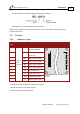
Table of Contents
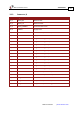
2.2.3. Feedback Options
• Incremental Encoder - up to 40 Mega-Counts per second
• Digital Halls - up to 2 kHz
• Incremental Encoder with Digital Halls for commutation - up to 40 Mega-Counts
• Interpolated Analog Sine/Cosine Encoder - up to 400 kHz
Internal Interpolation - up to x4096
Automatic correction of amplitude mismatch, signal offset
• Analog Halls
• Auxiliary Encoder inputs (ECAM, follower, etc.) single-ended, unbuffered
• The Bell 5 V power supply provides supply voltage (5 V, 200 mA max) for one
Encoder/Resolver/Hall Sensor
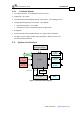
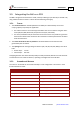
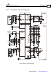
2.3. System Architecture
Controller
Main
12-95 VDC
Power supply
Optional
12-95 VDC
Auxiliary supply
I/Os
Communication
RS 232 and CANopen
Power Stage
Current
Feedback
Motor
Auxiliary
Encoder
Incremental
Encoder
Analog
Encoder
PWM
Protection
or
Figure 1: Bell System Block Diagram