
Installation Guide User Manual

Bell Installation Guide Installation
MAN-BELIG (Ver. 1.302
|www.elmomc.com
24
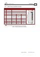
Table of Contents
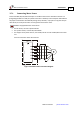
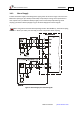
3.8. Auxiliary Supply (for Drive Logic)
Note: Notes for 12 ~ 95 VDC auxiliary supply connections:
The source of the 12 ~ 95 VDC Auxiliary Supply must be isolated.
Connect the VL and PR pins on the Bell in the manner described in Section 3.5 (Integrating the Bell
on a PCB).
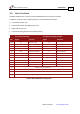
Pin Function Pin Positions
VL Auxiliary Supply Input
PR Supply Input Return
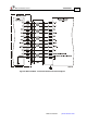
Power from the Bell to the motor must come from the
Main Supply and NOT from the Auxiliary Supply.
Table 2: Auxiliary Supply Pins
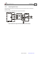
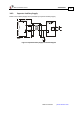
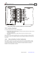
3.8.1. Single Supply
A single isolated DC power supply can provide power for both the main power and the Auxiliary
(Drive Logic) Supply. The drawing below shows how a single supply is connected.
Figure 6: Single Supply for both the Main Power Supply and the Auxiliary Supply