
Installation Guide User Manual

Bell Installation Guide Installation
MAN-BELIG (Ver. 1.302
|www.elmomc.com
27
Table of Contents
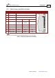
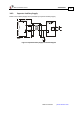
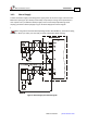
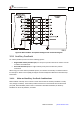
3.9. Main Feedback
The Main Feedback port is used to transfer feedback data from the motor to the drive.
The Bell can accept any of the following devices as a main feedback mechanism:
• Incremental encoder only.
• Incremental encoder with digital hall sensors.
• Digital hall sensors only.
• Incremental Analog (Sine/Cosine) encoder (option).
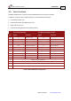
Incremental Encoder Interpolated Analog Encoder
Pin Signal Function Signal Function
J2/13 HC Hall sensor C input NC -
J2/11 HA Hall sensor A input NC -
J2/2 SUPRET Supply return SUPRET Supply return
J2/1 +5V Encoder/Hall +5V supply +5V Encoder/Hall +5V supply
J2/6 CHA- Channel A complement A- Sine A complement
J2/5 CHA Channel A A+ Sine A
J2/10 INDEX- Index complement R- Index complement
J2/9 INDEX Index R+ Index
J2/12 HB Hall sensor B input NC -
J2/8 CHB- Channel B complement B- Cosine B complement
J2/7 CHB Channel B B+ Cosine B
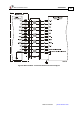
J2/3 ANALIN+ is used for Analog Input
J2/4 ANALIN- is used for Analog Input
J2/14 LED_2_OUT (AOKLED cathode) is used for LED indication
J2/15 LED_1_OUT (AOKLED anode) is used for LED indication
Table 3: Main Feedback Pin Assignments