
Installation Guide User Manual

Bell Installation Guide Bell Technical Specifications
MAN-BELIG (Ver. 1.302)
|www.elmomc.com
53
Table of Contents
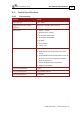
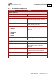
4.6. I/Os
The Bell has:
• 6 Digital Inputs
• 2 Digital Outputs
• 1 Analog Input
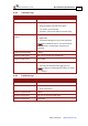
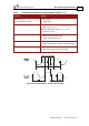
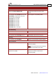
4.6.1. Digital Input Interfaces
Feature Details Connector
Location
Type of input
• Optically isolated
• All six inputs share one signal return line
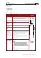
1.43K
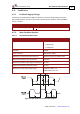
Digital Input
Schematic
Input current
for all inputs
Iin = 2.4 mA @ 5 V
High-level input
voltage
2.5 V < Vin < 10 V, 5 V typical
Low-level input
voltage
0 V < Vin < 1 V
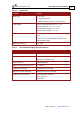
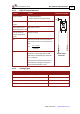
Minimum pulse
width
> 360 μsec
Execution time
(all inputs):
the time from
application of
voltage on input
until execution
is complete
If input is set to one of the built-in functions —
Home, Inhibit, Hard Stop, Soft Stop, Hard and Soft
Stop, Forward Limit, Reverse Limit or Begin —
execution is immediate upon detection:
0<T<360 μsec
If input is set to General input, execution depends
on the program. Typical execution time: ≅ 0.5
msec.
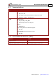
High-speed
inputs – 5 & 6
minimum pulse
width, in high-
speed mode
T < 5 µsec
Notes:
• Home mode is high-speed mode and can be
used for fast capture and precise homing.
• High speed input has a digital filter set to the
same value as the digital filter (EF) of the main
encoder.
• Highest speed is achieved when turning on the
optocouplers.