
Installation Guide Owner manual

Cello Installation Guide Installation
MAN-CELIG (Ver. 1.602)
www.elmomc.com
36
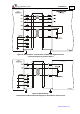
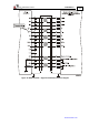
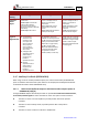
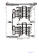
Below are the signals on the Auxiliary Feedback ports when set up to run as a buffered outputs
or emulated outputs of the main encoder (on FEEDBACK A):
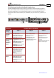
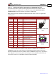
Port Pin Signal Function Pin Positions
B1 1 CHA Auxiliary channel
A high output
15-Pin High
Density D-Sub
Plug
B1 2 CHA- Auxiliary channel
A low output
B1 3 CHB Auxiliary channel
B high output
B1 4 CHB- Auxiliary channel
B low output
B1 5 INDEX Auxiliary Index
high output
B2 6 CHAO Buffered channel
A output
B2 7 CHAO- Buffered channel
A complement
output
PWR 8 +5V Encoder supply
voltage
PWR 9 SUPRET Encoder supply
voltage return
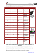
5
15
10
1
11
6
Port B1
Port B2
Power
15-Pin High
Density D-Sub
Socket
B1 10 INDEX- Auxiliary Index
low output
B2 11 CHBO Buffered channel
B output
B2 12 CHBO- Buffered channel
B complement
output
B2 13 INDEXO Buffered Index
output
B2 14 INDEXO- Buffered Index
complement
output
PWR 15 SUPRET Supply return
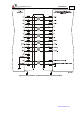
Table 8: Main Encoder Buffered Outputs or Emulated Encoder Outputs on FEEDBACK B - Pin
Assignments
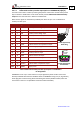
FEEDBACK B on the “top” of the Cello has a 15-pin high density D-Sub socket. Connect the
Auxiliary Feedback cable, from the controller or other device, to FEEDBACK B using a 15-pin
high density D-Sub plug with a metal housing. When assembling the Auxiliary Feedback cable,
follow the instructions in Section 3.4.4 (Feedback and Control Cable Assemblies).